
Stretching device

a stretching device and stretching technology, applied in the field of stretching devices, can solve the problems of difficulty in individual stretching extended controlled,

Active Publication Date: 2018-12-04
FOSTER THOMAS C
View PDF16 Cites 8 Cited by
  • Summary
  • Abstract
  • Description
  • Claims
  • Application Information

AI Technical Summary

Benefits of technology

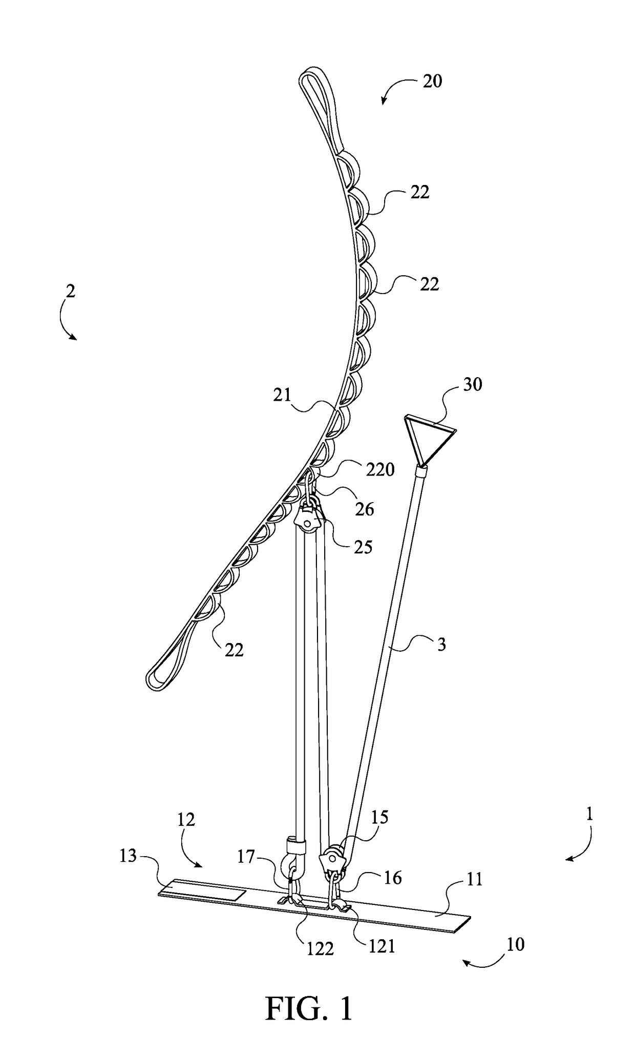
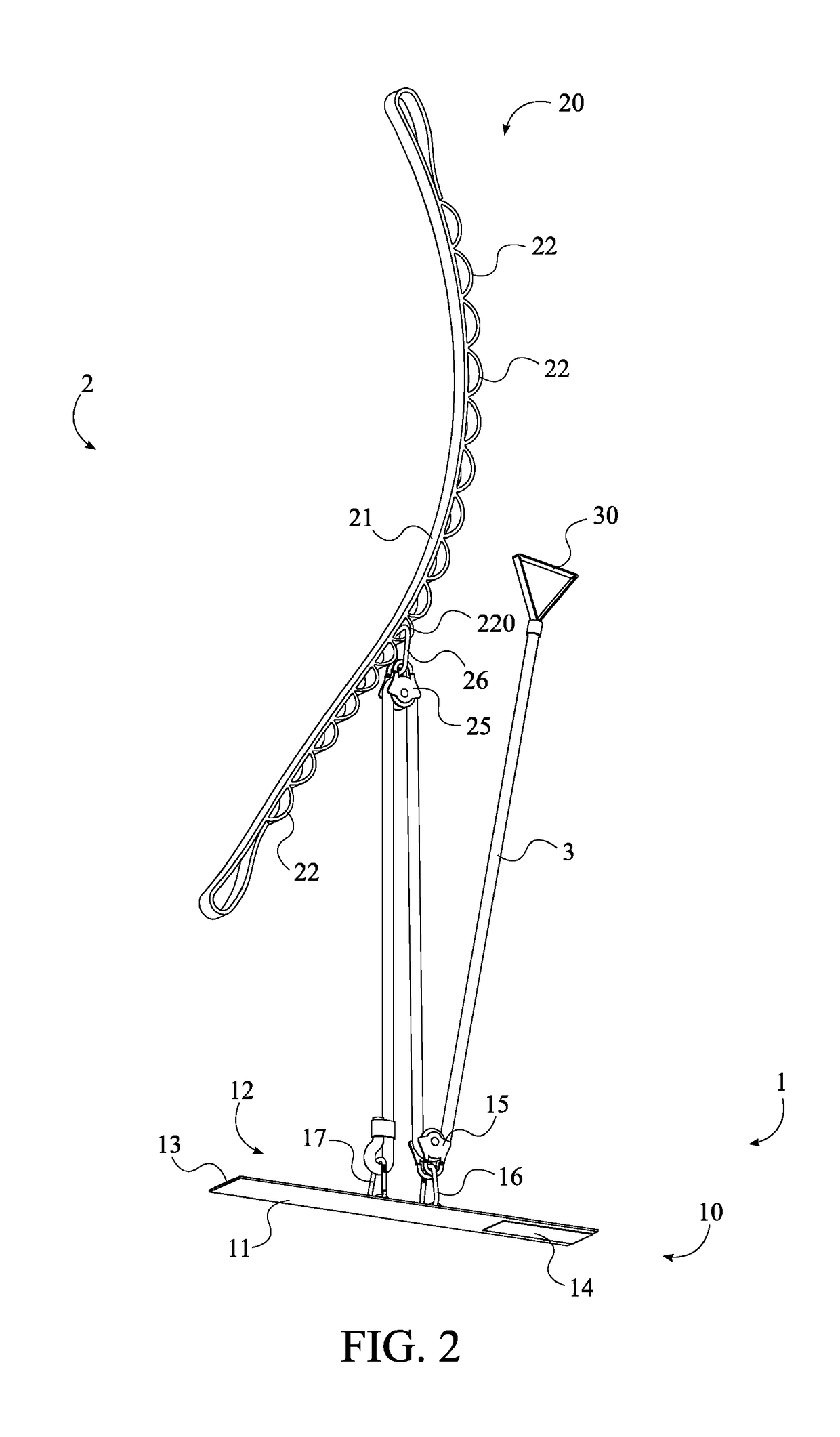
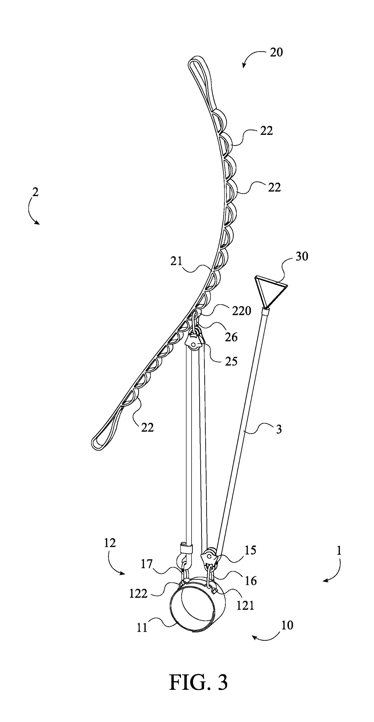
to provide a stretching device that uses a fixed anchor point, pulleys, a harness, and a motion transfer line to maximize the benefits that a user is able to achieve from a controlled stretch. A first anchor assembly includes a first anchor body and a first motion transfer pulley, while a second anchor assembly includes a second anchor body and a second motion transfer pulley; the first motion transfer pulley being attached to the first anchor body and the second motion transfer pulley being attached to the second anchor body. The first anchor body serves as the harness that is attached to the limb of the user, while the second anchor body serves as the fixed anchor point that is attached to a stationary object. The motion transfer line is terminally attached to the first anchor body and is trained around both the first motion transfer pulley and the second motion transfer pulley. By pulling the free end of the motion transfer line, the user can employ the mechanical advantages of the present invention to perform extended, controlled stretches.

Problems solved by technology

However, it is often difficult for an individual to perform extended controlled stretches, especially when attempting to stretch near or above the individual's comfort threshold.
This is typically due to the fatigue of maintaining a limb in the desired position for an extended period of time, or the inability of the individual to exert enough force in order to reach their comfort threshold.

Method used


Image

  • Stretching device
  • Stretching device
  • Stretching device

Examples


Embodiment Construction

[0014]All illustrations of the drawings are for the purpose of describing selected versions of the present invention and are not intended to limit the scope of the present invention.

[0015]The present invention is a stretching device that enables a user to employ the mechanical advantage of a multi-pulley system while performing various, prolonged muscle stretches. In addition to being used to stretch limbs the present invention can be repurposed as a lifting apparatus. Elderly patients and convalescents are able to anchor the adjustable anchor to an elevated anchor point and make use of the mechanical advantages afforded by the pulley system to lift and reposition limbs, or even entire bodies.

[0016]In order to provide the mechanical advantages, the present invention comprises a first anchor assembly 1, a second anchor assembly 2, and a motion transfer line 3. In reference to FIG. 1, the motion transfer line 3 is trained around the first anchor assembly 1 and the second anchor assemb...


PUM


Abstract

A stretching device that enables a user to employ the mechanical advantage of a multi-pulley system while performing various, prolonged muscle stretches; the stretching device including a first anchor assembly, a second anchor assembly, and a motion transfer line. The first motion transfer line has a first anchor body and a first motion transfer pulley; the first anchor body being attached to the user and the first motion transfer pulley being coupled to the first anchor body. Similarly, the second motion transfer line has a second anchor body and a second motion transfer pulley; the second anchor body being attached to a stationary object and the second motion transfer pulley being coupled to the second anchor body. The motion transfer line is terminally attached to the first anchor body and is trained around both the first motion transfer pulley and the second motion transfer pulley.

Description

[0001]The current application is a continuation in part of U.S. Utility patent application Ser. No. 15 / 637,680 filed on Jun. 29, 2017, which is a continuation of U.S. Utility patent application Ser. No. 15 / 461,254 filed on Mar. 16, 2017, which is a continuation of U.S. Utility patent application Ser. No. 15 / 157,840 filed on May 18, 2016, which claims a priority to the U.S. Provisional Patent application Ser. No. 62 / 163,003 filed on May 18, 2015.FIELD OF THE INVENTION[0002]The present invention relates generally to therapeutic stretching. More specifically, the present invention is a stretching device that can be anchored to a variety of objects for performing controlled stretches while providing a mechanical advantage.BACKGROUND OF THE INVENTION[0003]The practice of stretching one's body has many benefits for both athletic and therapeutic applications, such as loosening up limbs to prevent injury. Additionally, stretching can play an integral role in the rehabilitation of a body par...

Claims


Application Information

Patent Timeline
Patent Type & Authority Patents(United States)
IPC IPC(8): A61H1/02A63B21/00A63B23/00
CPCA61H1/0274A63B21/156A63B21/4013A63B21/4035A63B21/4021A63B2023/006A61H2201/1269A61H2201/1666A61H2201/0157A61H2201/1635A61H2201/1638A61H2201/165
Inventor FOSTER, THOMAS C.
Owner FOSTER THOMAS C
Learn More