
Lashing securement pin

a technology of securement pins and bolts, applied in the field of latching pins, can solve the problems of affecting the access of the bolt set, the size of the prior art bolted flange plate assembly, and the awkward attachment process, so as to facilitate the insertion of the anti-rotation member, facilitate the manual rotation of the cam disk, and facilitate the insertion

Active Publication Date: 2018-12-04
BNSF LOGISTICS
View PDF6 Cites 1 Cited by
  • Summary
  • Abstract
  • Description
  • Claims
  • Application Information

AI Technical Summary

Benefits of technology

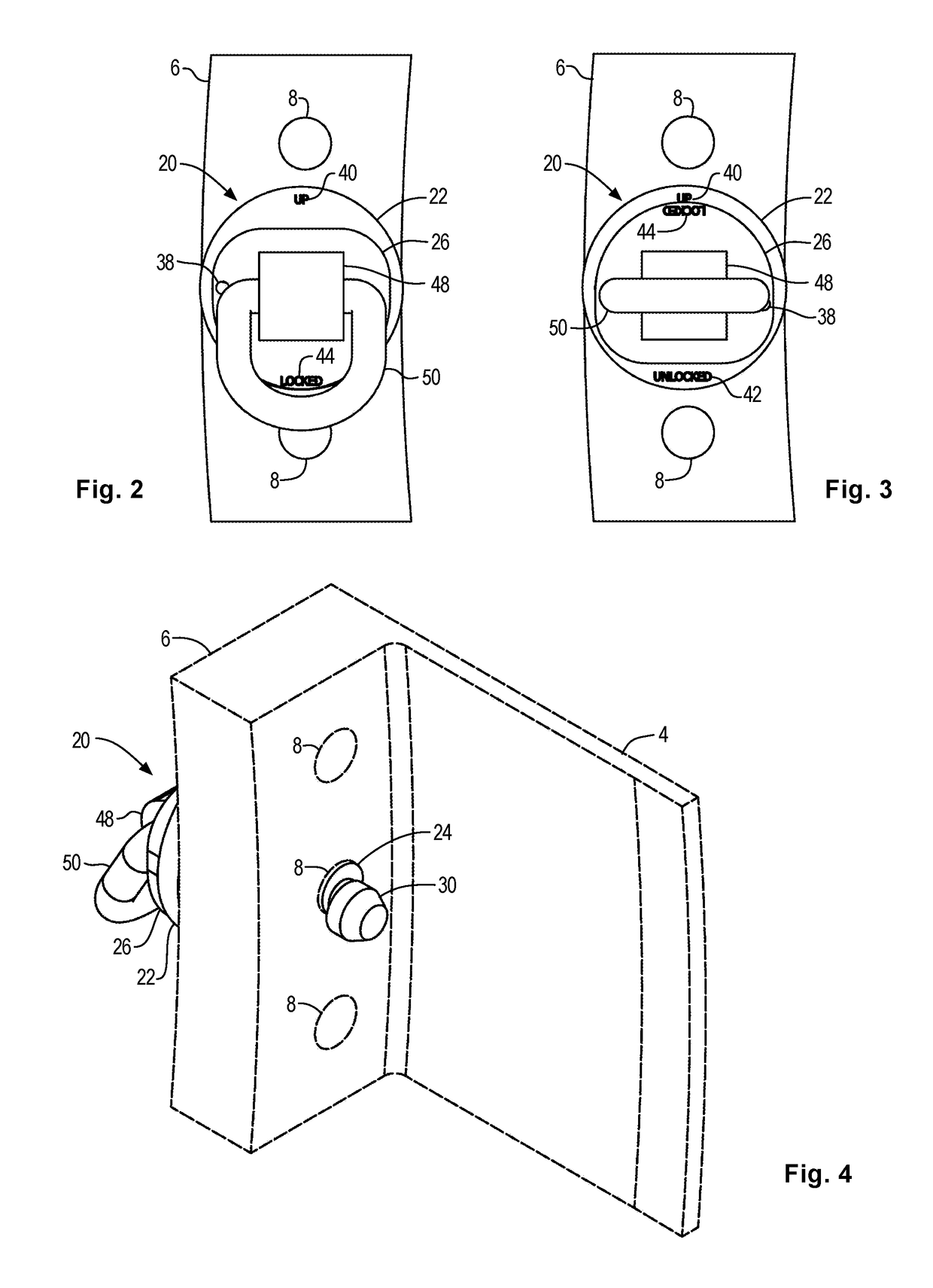
[0011]In a specific embodiment, the foregoing apparatus further includes a first hole formed through the flange and a second hole formed through the cam disk, and wherein the first hole and the second hole are aligned while the cam disk is located at the locked position. This alignment facilitates insertion of an anti-rotation member through both of the first hole and the second hole, which thereby prevents rotation of the cam disk away from the locked position. The anti-rotation member may be a lock, a cable, a chain, a rod, or other member suitable to prevent rotation.
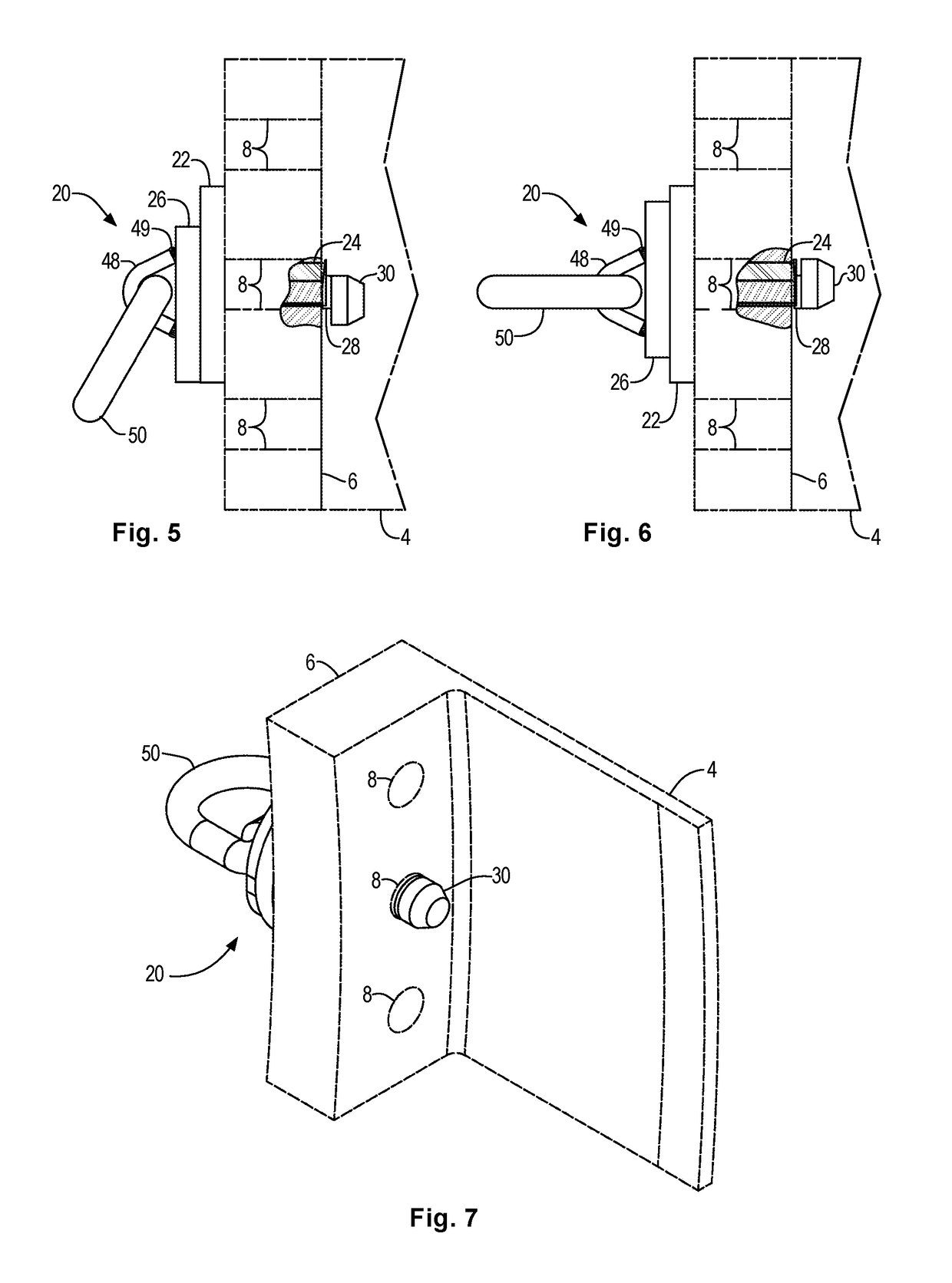
[0012]An illustrative embodiment of present disclosure teaches a lashing pin apparatus that retainably engages a hole formed through a member, such as an item of freight that is carried on a fixture or vehicle. The apparatus includes a cam pin sleeve with a flange at a proximal end thereof, and a cam pin hole formed eccentrically therethrough from the flange to a distal end thereof. The apparatus also includes a cam pin assembly that has a cam pin fixed between a cam disk at a proximal end and a cam eccentrically connected at a distal end thereof. The cam pin rotatably engages the cam pin hole and is aligned such that the cam disk is located adjacent to the flange and the cam is located adjacent to the distal end of the sleeve. Rotation of the cam disk with respect to the flange to an unlocked position aligns the cam with the sleeve to facilitate insertion though the hole in the member, and rotation of the cam disk to a locked position misaligns the cam with respect to the sleeve such that the cam engages the member against removal through the hole in the member. The apparatus also includes a metal clip fixed to the cam disk that retains a lashing ring, which facilitates manual rotation of the cam disk by rotating the lashing ring. The apparatus also includes an orientation mark disposed upon the flange to indicate a preferred orientation during manual insertion of the lashing pin apparatus through the hole in the member. The apparatus also includes an engagement indicator disposed on a proximate surface of the lashing pin apparatus that is revealed while the cam disk is located at the locked position, which provides an indication that the cam is misaligned with the sleeve and retained against removal through the hole in the member. The apparatus also includes a non-engagement indicator disposed on a proximate surface of the lashing pin apparatus that is revealed while the cam disk is located at the unlocked position, which provides an indication that the cam is aligned with the sleeve and enabled for insertion or removal through the hole in the member. In addition, the apparatus further includes a first hole formed through the flange and a second hole formed through the cam disk, wherein the first hole and the second hole are aligned while the cam disk is located at the locked position, to thereby facilitate insertion of an anti-rotation member through both of the first hole and the second hole, which prevents rotation of the cam disk away from the locked position.
[0013]An illustrative embodiment of the present disclosure teaches a method of connecting a lashing pin apparatus to a member having a hole formed therethrough, wherein the lashing pin apparatus includes a cam pin sleeve with a flange at a proximal end thereof and a cam pin hole formed eccentrically therethrough from the flange to a distal end thereof, and wherein the lashing pin apparatus further includes a cam pin assembly with a cam pin fixed between a cam disk at a proximal end and a cam eccentrically connected at a distal end thereof, and wherein the cam pin rotatably engages the cam pin hole and is aligned such that the cam disk is located adjacent the flange and the cam is located adjacent to the distal end of the sleeve. The method includes the steps of rotating the cam disk with respect to the flange to an unlocked position aligning the cam with the cam sleeve, then inserting the distal end of the lashing pin apparatus through the hole in the member, and rotating the cam disk with respect to the flange to a locked position misaligning the cam with the cam sleeve, thereby engaging the cam with the member and preventing removal of the lashing pin apparatus from the hole in the member.
[0018]In a specific embodiment of the foregoing method, wherein the lashing pin apparatus includes a non-engagement indicator disposed on a proximate surface of the lashing pin apparatus that is revealed while the cam disk is located at the unlocked position, the method further includes rotating the cam disk to reveal the non-engagement indicator, thereby providing an indication that the cam is aligned with the sleeve and enabling insertion or removal through the hole in the member.

Problems solved by technology

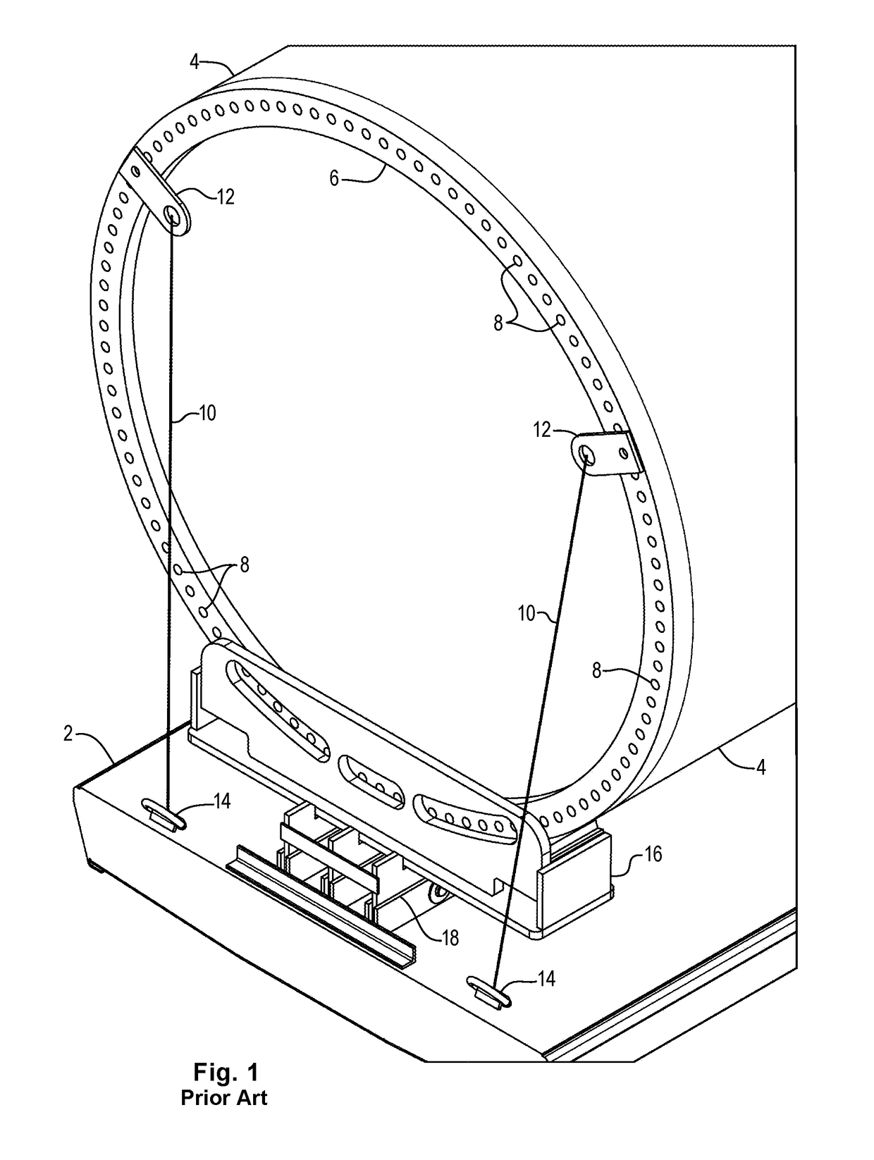
The prior art bolted flange plate assemblies are quite large.
Furthermore, the fastening points are typically located high on the railcar, making the attachment process awkward.
Additionally, tower ends are normally covered with protective tarpaulins, which interfere with access for connecting the bolt sets.
This requires provisions for gaining access to the flange holes on the tower section, which is time consuming and may damage the tarpaulins.

Method used


Image

  • Lashing securement pin
  • Lashing securement pin
  • Lashing securement pin

Examples


Embodiment Construction

[0032]Illustrative embodiments and exemplary applications will now be described with reference to the accompanying drawings to disclose the advantageous teachings of the present invention.

[0033]While the present invention is described herein with reference to illustrative embodiments for particular applications, it should be understood that the invention is not limited thereto. Those having ordinary skill in the art and access to the teachings provided herein will recognize additional modifications, applications, and embodiments within the scope hereof and additional fields in which the present invention would be of significant utility.

[0034]In considering the detailed embodiments of the present invention, it will be observed that the present invention resides primarily in combinations of steps to accomplish various methods or components to form various apparatus and systems. Accordingly, the apparatus and system components, and method steps, have been represented where appropriate ...


PUM


Abstract

A lashing pin for engaging a hole in member to facilitate lashing the member to a fixture or vehicle. The lashing pin combines a cam pin sleeve assembly having a flange and sleeve with an eccentric hole formed therethrough with a cam pin assembly having a cam pin passing through the eccentric hole and connecting a cam disk with an eccentrically mounted cam. Rotation of the cam disk with respect to the flange aligns and misaligned the cam with respect to the cam sleeve, thereby enabling insertion through the hole at first position, and retention of the cam against removal at a second position.

Description

BACKGROUND OF THE INVENTIONRelated Applications[0001]None.Field of the Invention[0002]The present invention relates to securing loads for transportation using lashing lines. More particularly, the present invention relates to a lashing pin that is retained in a hole of a member by a cam, which is useful in lashing wind turbine tower sections to railcars by engaging a bolt hole in a flange.Description of the Related Art[0003]The prior art processes for securing wind turbine tower sections to railcars included bolting tie down plates to the flanges at each end of a tower section using a bolt, washer, and nut set. The tie down plates serve as a connection points that are lashed to the railcar using lashing lines. This is necessary to prevent the tower section from rolling off the railcar, or railcar fixture, during transport. Similar lashing techniques are employed for a wide range of cargo carried on a wide range of vehicles and loading fixtures, as are known to those skilled in the a...

Claims


Application Information

Patent Timeline
Patent Type & Authority Patents(United States)
IPC IPC(8): B60P7/08F16B13/04F16B13/10
CPCB60P7/0807B60P7/0823F16B13/04Y10T24/42F16B2013/10B61D45/001F16B13/10
Inventor LANDRUM, SCOTT C.JONES, III, JAMES H.SCHULTZ, DALE G.
Owner BNSF LOGISTICS
Learn More