Structure monitoring

a technology for monitoring structures and structures, applied in the field of structure monitoring, can solve the problems of prohibitively high cost, no successful deployment of such a system, and the inability to properly monitor the risers of the subsea,

Active Publication Date: 2018-12-04
SILIXA +1
View PDF54 Cites 15 Cited by
  • Summary
  • Abstract
  • Description
  • Claims
  • Application Information

AI Technical Summary

Benefits of technology

[0011]With the above the shape and position of a structure such as a sub-sea riser can be monitored in a convenient manner. In this respect, sub sea risers often have fiber optic cables passing through them, which may be used as the fiber optic cable of the DAS system. Moreover, such fiber optic DAS systems can resolve acoustic signals with a spatial resolution of better than lm, and hence high spatial resolution monitoring of the structure position and movement can be obtained. This allows for advanced fatigue monitoring and logging, and other such analysis, to take place.
[0016]In some embodiments the subsets of sensors may be contiguous along the fiber, whereas in other embodiments the subsets of sensors may overlap, such that any one acoustic sensor is a member of more than one subset. In this latter case, more positions of points along the fiber can be obtained, and hence spatial resolution is increased.

Problems solved by technology

However, the length of many risers means that for proper tracking many individual hydrophones are required along the length of the riser, which heretofore has been prohibitively expensive.
Thus, both acoustic positioning and the concept of the monitoring of subsea risers using active hydro acoustics are known in theory, but heretofore no successful deployment of such a system has taken place.
As noted above, the number of hydrophones required to properly monitor a subsea riser has been prohibitive, and there are challenging deployment issues.
Therefore, whilst positioning per se using optical fibre acoustic sensors has been suggested in the prior art, there is still no solution which allows for proper monitoring of a riser or other structure along its whole length, and which particularly allows for fatigue analysis, for example, to take place.

Method used


Image

  • Structure monitoring
  • Structure monitoring
  • Structure monitoring

Examples


first embodiment

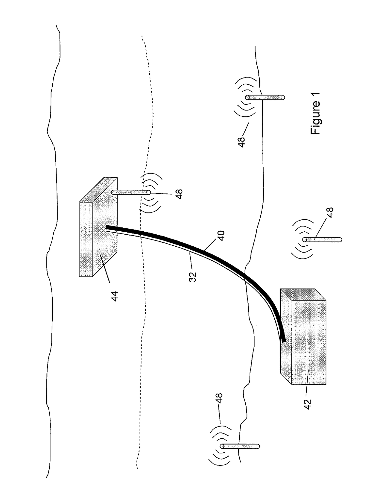
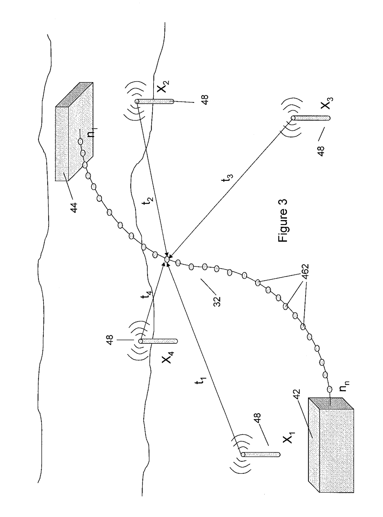
[0065]FIG. 3 illustrates the operating environment of a Here, fiber 32 attached to or otherwise related in a known manner to a subsea riser (not shown) extends from surface vessel 44 to seafloor installation 42. The fiber 32 forms part of a DAS, as described above, that is able to sense an incident vibro acoustic field with a spatial resolution of approximately 1 m. Hence, an acoustic sensor 462 is formed approximately every 1 m along fiber 32, to give n acoustic sensors along the length of fiber 32.

[0066]Also provided are x acoustic sources Xn (48), with four such sources being shown in FIG. 3. Each acoustic source is at a known location, and emits an identifiable acoustic signal, for example at a specific, known, frequency, or of a particular pattern.

[0067]In a first embodiment of the invention, each sensor 462 is treated individually, and a respective location found for a particular sensor without reference to positions found for other sensors on the fibre. FIG. 4 illustrates th...

third embodiment

[0074]FIGS. 6 and 7 illustrate the concept of the Specifically, contiguous groups of sensors 462 along the fiber 32 are grouped together into a virtual small line array sensor 62. An incident acoustic wave incident on the line array sensor 62 will cause an output from each of the sensors at different times, dependent on the angle of incidence of the wave. Hence, as shown in FIG. 6, an incident wave 64 incident on line array 62 at the angle shown will first cause a signal from sensor 622 , followed by sensor 624, 628, and finally 630. Moreover, the time delay δ between each sensor being triggered is a cosine function of the direction of travel of the wave, whereby the angle of incidence of the wave can be determined from the order in which the sensors give an output and the time delay between sensor outputs along the array. In this respect, it is assumed that the array size is small enough so as to be considered to be in the far field of the incident wave.

[0075]FIGS. 8 and 9 illustr...


PUM

PropertyMeasurementUnit
frequenciesaaaaaaaaaa
lengthaaaaaaaaaa

Abstract

A method and apparatus for monitoring a structure using an optical fiber based distributed acoustic sensor (DAS) extending along the length of the structure. The DAS is able to resolve a separate acoustic signal with a spatial resolution of 1 m along the length of the fibre, and hence is able to operate with an acoustic positioning system to determine the position of the riser with the same spatial resolution. In addition, the fiber can at the same time also detect much lower frequency mechanical vibrations in the riser, for example such as resonant mode vibrations induced by movement in the surrounding medium. By using vibration detection in combination with acoustic positioning then overall structure shape monitoring can be undertaken, which is useful for vortex induced vibration (VIV) visualisation, fatigue analysis, and a variety of other advanced purposes. The structure may be a sub-sea riser.

Description

TECHNICAL FIELD[0001]The present invention relates to the monitoring of structures such as, for example, sub-sea risers, and particularly to a method and apparatus for monitoring structures using an optical fiber distributed acoustic sensor (DAS) capable of detecting sound at short intervals along the length of the structure. In one embodiment the DAS system is employed as part of an acoustic positioning system to help determine the shape of the structure along its length. In another embodiment the DAS system is employed to monitor mechanical vibration of the structure itself. In a preferred embodiment both vibration monitoring and acoustic positioning are undertaken by the same DAS equipment.BACKGROUND TO THE INVENTION AND PRIOR ART[0002]Sub-sea risers are used to transport materials between the seafloor and the surface (and vice versa), and are used extensively in the oil and gas industries. They come in several different variants, and are used for many purposes, particularly the ...

Claims


Application Information

Patent Timeline
Patent Type & Authority Patents(United States)
IPC IPC(8): G01N29/24E21B47/00G01S5/18E21B47/09G01S5/30G01S5/26G01H9/00G01D5/353
CPCG01N29/2418E21B47/0006E21B47/091G01H9/004G01S5/186G01S5/26G01S5/30G01S5/18G01D5/35383E21B47/007E21B47/095G01D5/353E21B47/0224
Inventor FARHADIROUSHAN, MAHMOUDFINFER, DANIELKAMIL, YOUSIFKUTLIK, ROY LESTER
Owner SILIXA
Why Eureka
Try Eureka