Supercharge Your Innovation With Domain-Expert AI Agents!

Vehicle heat exchanger

a heat exchanger and vehicle technology, applied in indirect heat exchangers, lighting and heating apparatus, transportation and packaging, etc., can solve the problems of uneven temperature distribution of air passing through the heat exchanger, etc., and achieve the effect of reducing temperature variation

Active Publication Date: 2018-12-11
HANON SYST
View PDF18 Cites 0 Cited by
  • Summary
  • Abstract
  • Description
  • Claims
  • Application Information

AI Technical Summary

Benefits of technology

The present invention results in a more uniform temperature distribution in the heat exchanger. This is achieved by creating a parallel flow in which the refrigerant is distributed to opposite sides of the heat exchangers and a counter flow in which the refrigerant flows in opposite directions. This reduces the variation in temperature in the overlapping region of the heat exchangers and ensures a uniform distribution of air temperature. This enables the discharge of cold air with a uniform temperature, regardless of the position of the vent.

Problems solved by technology

However, if the temperature in an evaporator is not uniformly distributed, the temperature distribution of air passing through a heat exchanger is not uniform and hence the temperature of discharged air may vary depending on the vents.
For this reason, the temperature distribution in the heat exchanger may not be uniform, and the temperature distribution of air passing through the heat exchanger may not be uniform.

Method used


Image

  • Vehicle heat exchanger
  • Vehicle heat exchanger
  • Vehicle heat exchanger

Examples


first embodiment

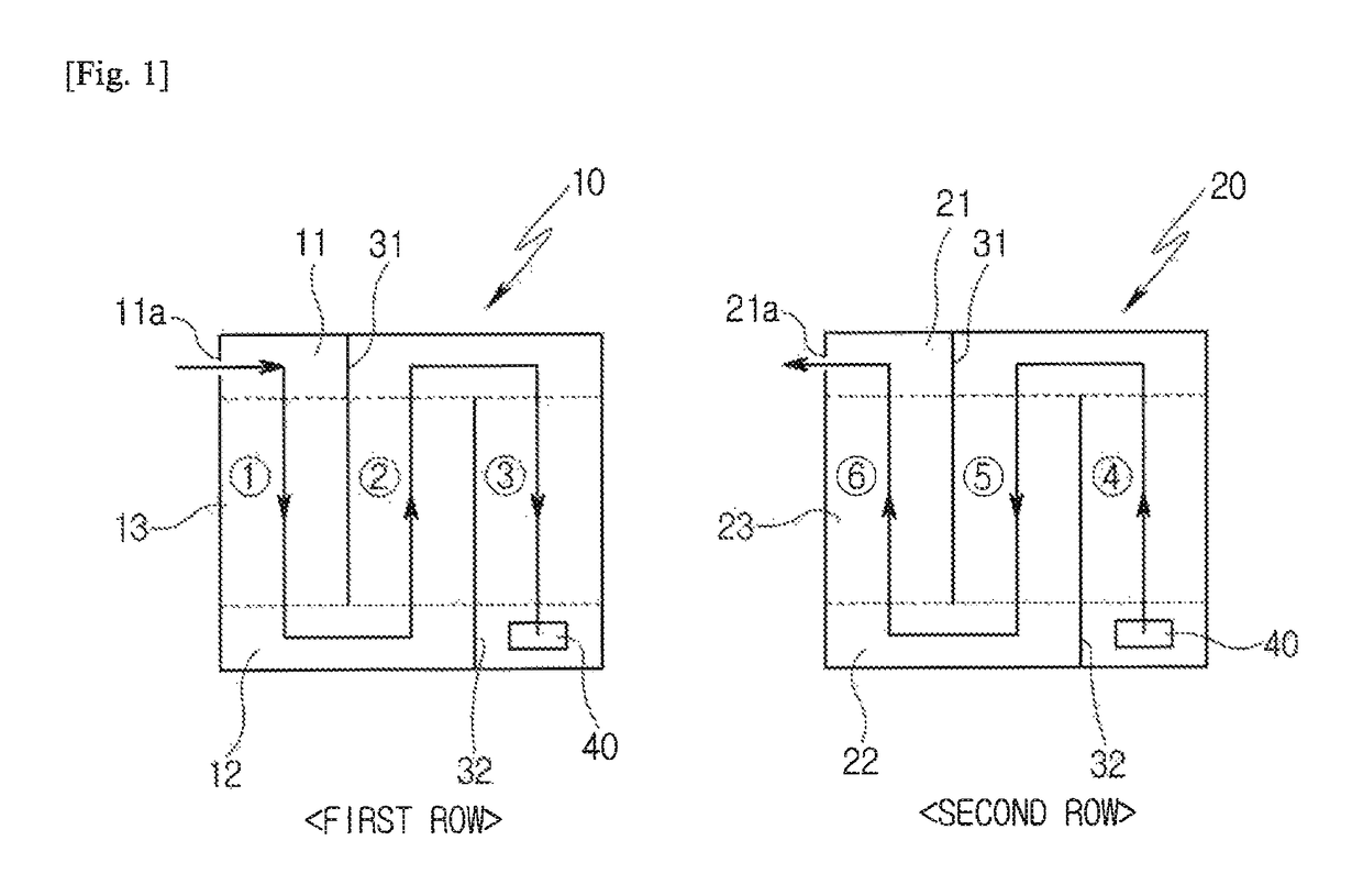
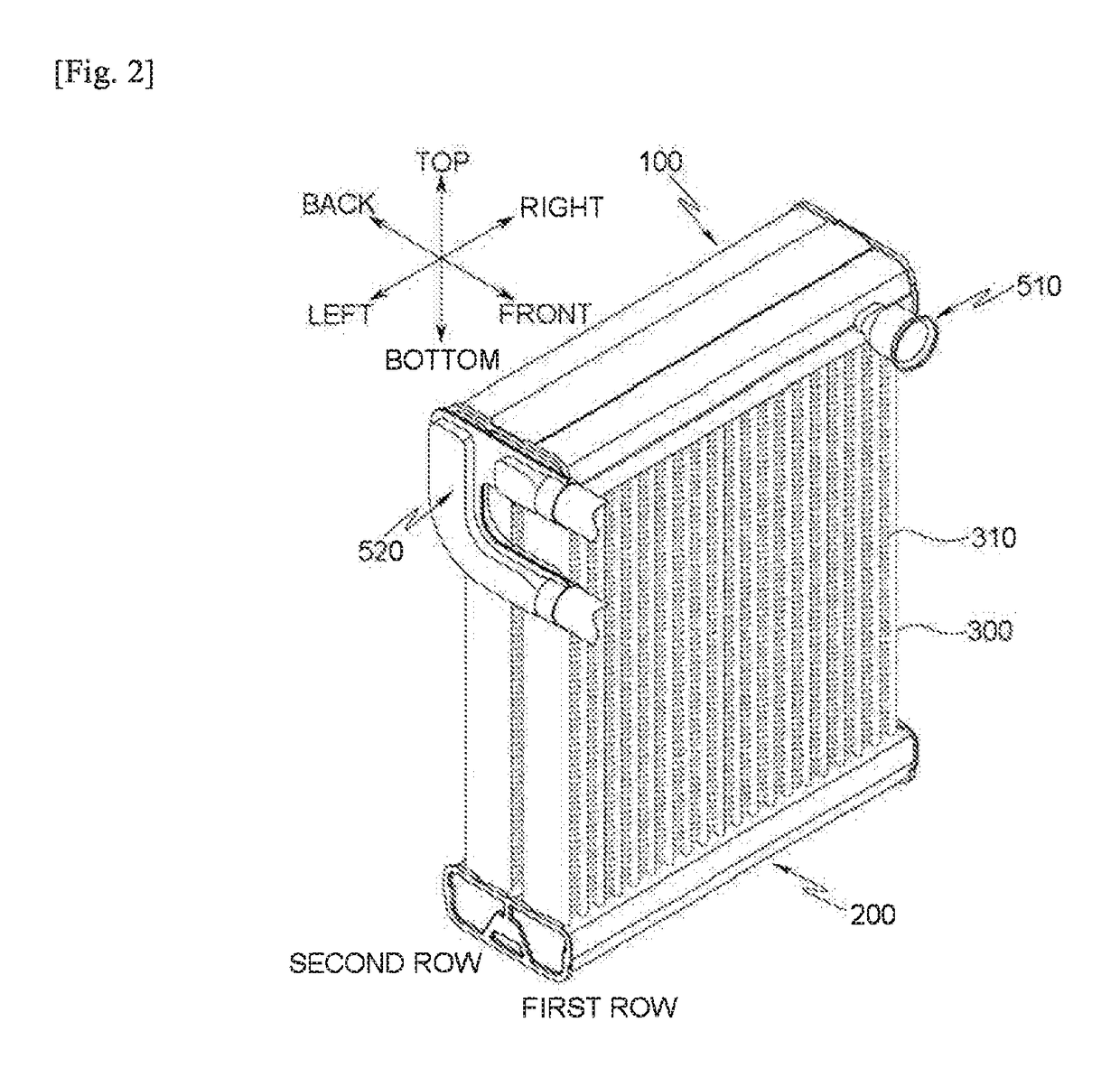
[0048]Hereinafter, a heat exchanger according to the present invention will be described with reference to FIGS. 5 to 9, wherein the heat exchanger has the double row structure that includes the upper and lower header tanks 100 and 200 each having the three-space structure as described above.

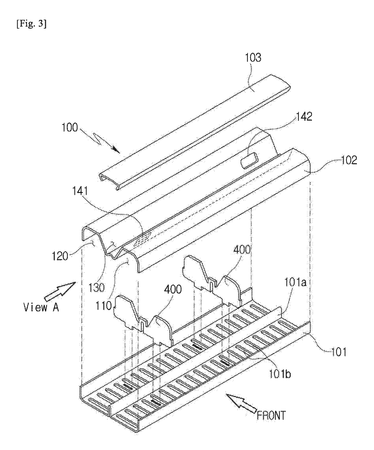
[0049]The upper header tank 100 has a first communication hole 141 that is formed in one end between the first row upper space 110 and the upper intermediate space 130, a second communication hole 142 that is formed in the other end between the second row upper space 120 and the upper intermediate space 130, and a refrigerant inlet 143 that is formed at one side of the upper intermediate space 130.

[0050]The lower header tank 200 has a first communication hole 241 that is formed in one end between the first row lower space 210 and the lower intermediate space 230, a second communication hole 242 that is formed in the other end between the second row lower space 220 and the lower intermediate spac...

second embodiment

[0064]Hereinafter, a heat exchanger according to the present invention will be described with reference to FIGS. 10 to 12, wherein the heat exchanger has the double row structure that includes the upper and lower header tanks 100 and 200 each having the three-space structure as described above.

[0065]The upper header tank 100 has a first communication hole 141 that is formed in one end between the first row upper space 110 and the upper intermediate space 130, and a second communication hole 142 that is formed in the other end between the second row upper space 120 and the upper intermediate space 130.

[0066]Both refrigerant inlet and outlet 111 and 121 are formed in the upper header tank 100. The refrigerant inlet 111 is formed in an end opposite to the first communication hole 141 in the first row upper space 110, and the refrigerant outlet 121 is formed in a portion close to the second communication hole 142 in the second row upper space 120. That is, the refrigerant inlet and outl...


PUM


Abstract

The present invention relates to a heat exchanger for a vehicle, in which a refrigerant is introduced into a first row heat exchanger and a second row heat exchanger and flows in opposite directions, thereby improving uniformity of temperature distribution.

Description

[0001]This application is a § 371 of International Application No. PCT / KR2016 / 002650 filed Mar. 16, 2016, and claims proirity from Korean Patent Application No. 10-2015-0038218 filed Mar. 19, 2015.TECHNICAL FIELD[0002]The present invention relates to a heat exchanger for a vehicle, and more particularly, to a heat exchanger for a vehicle in which air passing therethrough has a uniform temperature distribution.BACKGROUND ART[0003]Vehicles are equipped with air conditioners for cooling and dehumidification in the summer.[0004]Air conditioners include compressors, condensers, expansion valves, and evaporators, circulate refrigerant through them, and supply cold air, which is generated by absorbing ambient heat when the refrigerant evaporates in the evaporators, to the interior.[0005]The temperature of air discharged to the interior is preferably uniform regardless of the position of each vent. However, if the temperature in an evaporator is not uniformly distributed, the temperature di...

Claims


Application Information

Patent Timeline
Patent Type & Authority Patents(United States)
IPC IPC(8): B60H1/32F28D21/00F28D1/053F28F9/02
CPCB60H1/3227F28D1/05391F28F9/0202F28F9/0204F28F9/028F28F9/0224F28F9/026F28F2250/102F28D2021/0085F28F9/0212F25B39/02F28F9/22F25B2339/02F28F2009/222B60H1/00035F28D1/0435F28F9/0219F28F9/0251B60H2001/00121
Inventor JEON, YOUNG-HAGU, JUNG SAMSHIN, HYUN KUNOH, KWANG HUN
Owner HANON SYST
Features
  • R&D
  • Intellectual Property
  • Life Sciences
  • Materials
  • Tech Scout
  • Unparalleled Data Quality
  • Higher Quality Content
  • 60% Fewer Hallucinations
Learn More