Method for forming a wrench end

a technology of forming method and wrench end, which is applied in the direction of wrenches, cutting tools, manufacturing tools, etc., can solve the problems of increasing the cost of forming wrenches and reducing processing efficiency, so as to increase processing and forming efficiency, and quickly form wrenches end

Active Publication Date: 2018-12-18
CHEN MING CHANG
View PDF8 Cites 1 Cited by
  • Summary
  • Abstract
  • Description
  • Claims
  • Application Information

AI Technical Summary

Benefits of technology

[0005]An object of this invention is to provide a method for forming a wrench end quickly and increasing the efficiency of processing and forming the wrench.
[0007]The successive steps, as aforementioned, can facilitate a concurrent shaping of the wrench-shaped part and the hole on the head of the blank and can be distinguished in comparison with the traditional method which requires the steps of forming the wrench outline and hole in sequence and finally removing residual material from the outline. Therefore, the efficiency of processing the wrench is largely promoted. The shaping step as claimed can subject the partial surface of the head whose shape is changed by bending to a squeezing force whereby the interior structure of the portions of the head, namely the bent parts, comes together to provide a denser performance and the quality of the shaped wrench becomes better.
[0008]Preferably, in one embodiment, the initially press-forging step can be performed by press-forging two ends of the flat blank at the same time, thereby forming two opposite heads with respective wrench-shaped parts and holes on the flat blank. Subjecting the two heads to a bending action can also be allowed to provide the heads with respective curved sections and stretched sections bent at different angles. In case of two heads, the curved section and stretched section of each head can be enclosed and held by the gripping apparatus and then be gradually squeezed under a pressing force of the punch imparted to the hole of each head. Therefore, the change in the interior structure of the curved sections and the stretched sections can be incurred to provide a denser arrangement which allows the curved sections, the stretched sections and the holes to be well shaped in order to increase the quality of the formed wrench.

Problems solved by technology

Generally, the traditional method requires complex steps and needs to use multiple presses for completing the processing work, with the result that the processing time is prolonged, the processing efficiency is reduced, and the cost for forming the wrench is increased.

Method used


Image

  • Method for forming a wrench end
  • Method for forming a wrench end
  • Method for forming a wrench end

Examples


Embodiment Construction

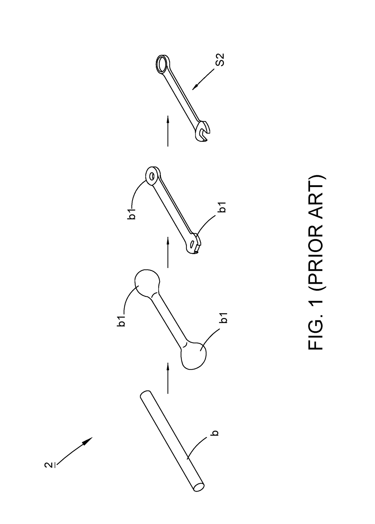
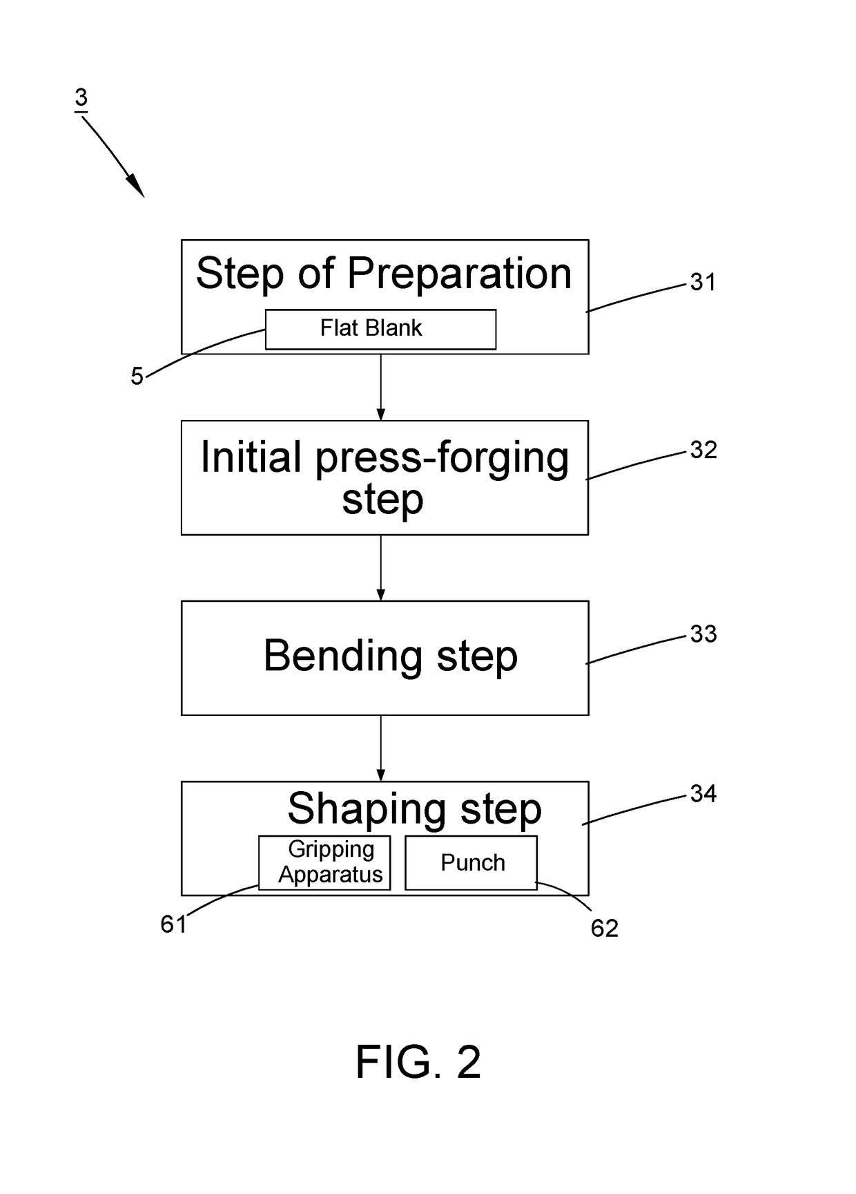
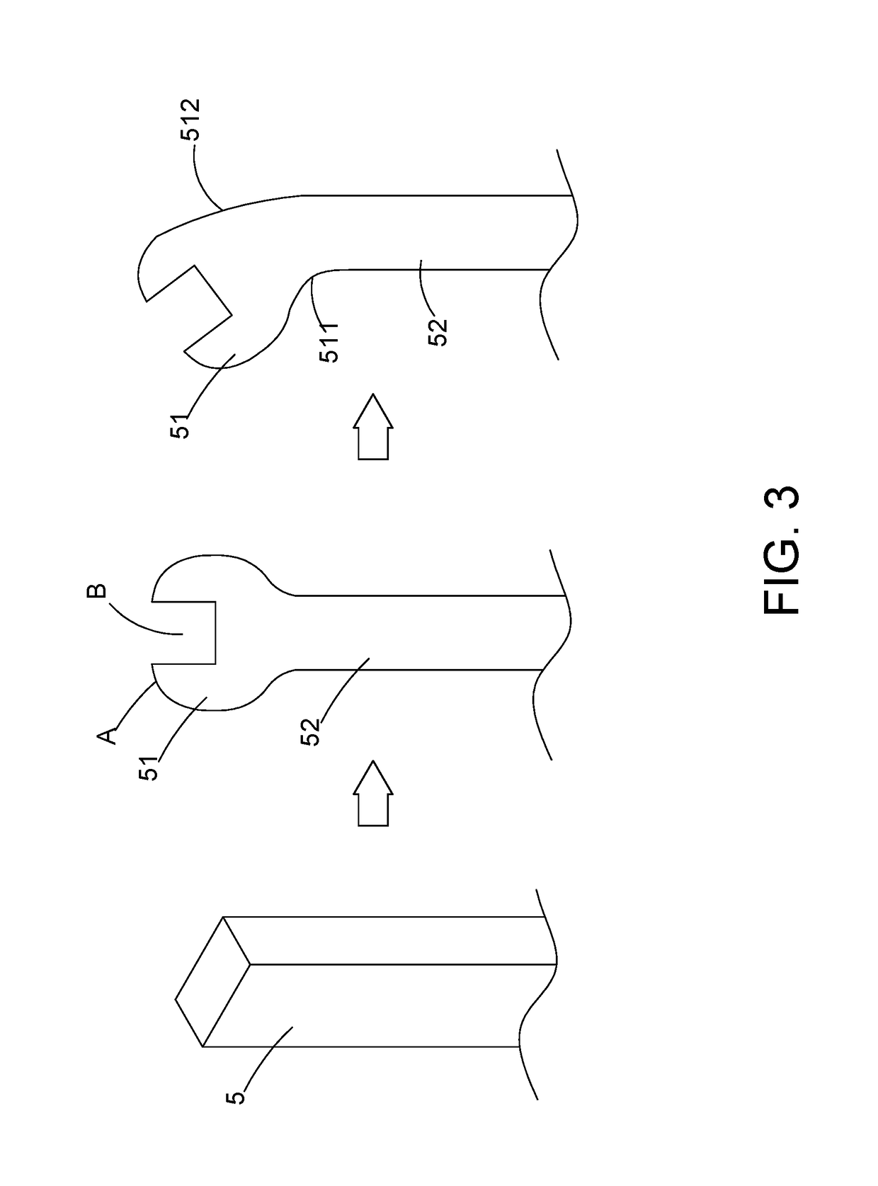
[0015]Referring to FIG. 2, a method 3 for forming a wrench end of a first preferred embodiment of this invention includes a step of preparation 31, an initial press-forging step 32, a bending step 33 and a shaping step 34. As shown in FIG. 3, the step of preparation 31 is performed by preparing a blank 5. The blank 5 is in a flat shape, preferably in a rectangular and level contour as shown, thereby being conducive to a direct pressing action. After the preparation step 31, the step 32 is performed by initially press-forging at least one end of the flat blank 5 in order to divide the flat blank 5 into a head 51 and a shank 52 extending outwards from the head 51. Specifically, the head 51 is pressed to have a wrench-shaped part A and also form a hole B while the wrench-shaped part A is formed. In the embodiments of this invention, only the end of the blank 51 is pressed to form the head 51, and the non-pressed remainder of the blank 51 is configured for the shank 52 extending from th...


PUM

PropertyMeasurementUnit
timeaaaaaaaaaa
shapeaaaaaaaaaa
shapesaaaaaaaaaa

Abstract

A method for forming a wrench end includes the steps of preparing a flat blank, initially press-forging at least one end of the blank to form a head with a wrench-shaped part and a hole on the blank, bending the head to form a curved section and a stretched section which are bent at different angles, and shaping the head by holding the curved section and the stretched section with a gripping apparatus and then pressing the hole of the head with a punch in order to subject the two sections to a squeezing force whereby the sections can have a denser interior structure and facilitate a final shaping of the head. The method facilitates a quick shaping of the wrench end and increases the efficiency of forming a wrench product.

Description

BACKGROUND OF THIS INVENTION[0001]1. Field of this Invention[0002]This invention relates to a forming method and relates particularly to a method for forming a wrench end.[0003]2. Description of the Related Art[0004]Referring to FIG. 1, a traditional method 2 for forming a wrench is carried out by cold forging and includes a preparing step, a head forming step, a stamping step and a removing step. The preparing step is performed by preparing a round metal blank b. The head forming step is executed by cold-forging two ends of the round metal blank b with a press (not shown) to form two round heads b1. The stamping step is performed by pressing the round metal blank b having two round heads b1 with a stamping press (not shown) whereby the round metal blank b is formed into a flat blank having a wrench outline. The removing step is executed by removing residual material from the peripheral edge of the wrench outline of the flat blank with another stamping press (not shown). Therefore, ...

Claims


Application Information

Patent Timeline
Patent Type & Authority Patents(United States)
IPC IPC(8): B21K5/16B25B13/08B22F3/10
CPCB25B13/08B21K5/16
Inventor CHEN, MING-CHANG
Owner CHEN MING CHANG
Why Eureka
Try Eureka