Method of manufacturing a bundle of electrospun yarn and manufacturing equipment for the same

a technology of electrospun yarn and manufacturing equipment, which is applied in the direction of filament/thread forming, textiles and papermaking, fibre treatment, etc., can solve the problem of limited conventional electrospinning method

Active Publication Date: 2018-12-18
NAT TAIWAN UNIV OF SCI & TECH
View PDF4 Cites 0 Cited by
  • Summary
  • Abstract
  • Description
  • Claims
  • Application Information

AI Technical Summary

Benefits of technology

[0007]In order to solve the disadvantages and shortcomings of the conventional nanofiber, the present invention provides a method of manufacturing a bundle of electrospun yarn that provides a preferred strength and that makes producing nanofibers as a woven product possible.

Problems solved by technology

However, the conventional electrospinning method is limited by the drawbacks of process.

Method used


Image

  • Method of manufacturing a bundle of electrospun yarn and manufacturing equipment for the same
  • Method of manufacturing a bundle of electrospun yarn and manufacturing equipment for the same
  • Method of manufacturing a bundle of electrospun yarn and manufacturing equipment for the same

Examples


first embodiment

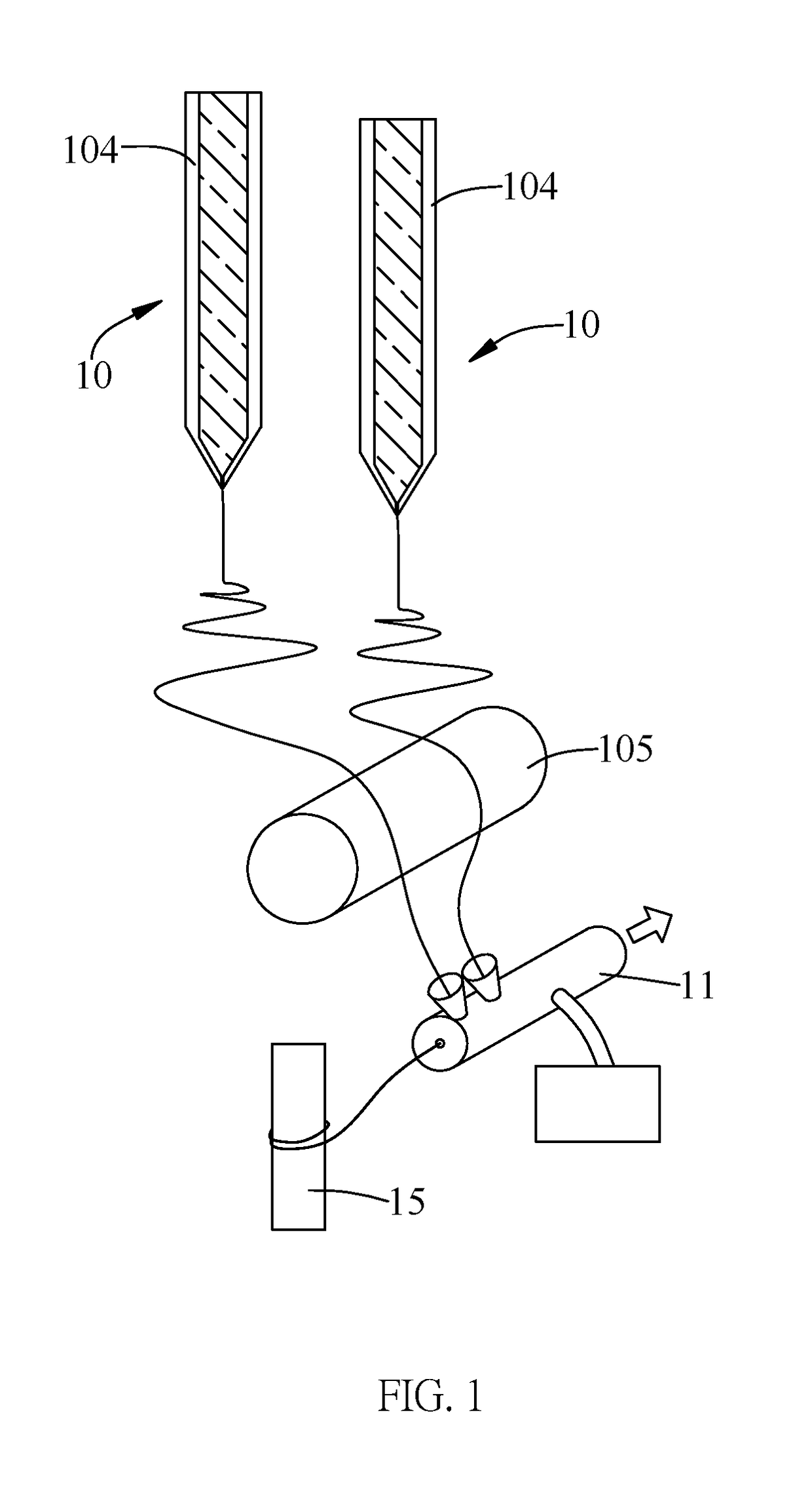
[0030]In the vortex containing device 11, the vortex containing device 11 is a hollow tube with a feeding end, an exporting end and an air hole. The electrospun fiber E is drawn into the hollow tube of the vortex containing device 11 via the feeding end. The gas that is stored in the hollow tube may be compressed to form a convergent-divergent channel hollow tube via the air hole by the vortex generator. The compressed gas will form two vortexes with opposite rotating directions along with an axial direction in the hollow tube. Thus, the bundle of the electrospun yarn may be formed by the vortexes with opposite rotating directions in the vortex containing device 11.

second embodiment

[0031]In the vortex containing device 11, the vortex containing device 11 is a hollow tube with multiple feeding ends, an exporting end and an air hole. The electrospun fibers are respectively drawn into the hollow tube via multiple electrospinning devices 10. The gas that is stored in the hollow tube may be compressed to form a convergent-divergent channel via the air hole by the vortex hollow tube. The compressed air will form two vortexes with opposite rotating directions along with an axial direction in the hollow tube. Thus, the bundle of the electrospun yarn may be formed by the vortexes with opposite rotating directions in the vortex containing device 11.

third embodiment

[0032]In the vortex containing device 11, the vortex containing device 11 may be a tank with a feeding end and an exporting end. The tank contains a liquid vortex generated by the vortex generator. The electrospun fiber is drawn into the tank by the liquid vortex via the feeding end. Thus, the bundle of the electrospun yarn may be formed by the liquid vortex.


PUM

PropertyMeasurementUnit
pressureaaaaaaaaaa
winding speedaaaaaaaaaa

Abstract

An equipment of manufacturing a bundle of electrospun yarn has a vortex containing device and a bundles collecting device. The vortex containing device has a feeding end, an exporting end and a vortex generator. The vortex generator is mounted in and communicates with the vortex containing device to form a fluid vortex in the vortex containing device to provide a guiding force. The guiding force draws an electrospun fiber into the feeding end of the vortex containing device. The electrospun fiber is wound to form a bundle of electrospun yarn by the fluid vortex. The bundles collecting device is rotated to collect the bundle of electrospun yarn.

Description

BACKGROUND OF THE INVENTION[0001]1. Field of the Invention[0002]The present invention relates to a method of manufacturing a bundle of electrospun yarn.[0003]2. Description of Related Art[0004]Electrospun fibers and related fiber webs are serving mostly as carriers of drugs, dispersion media of different additives (nanodots, antimicrobial particles etc) and the like. For certain applications, it is of interest and important to electrospin alternative structures instead of the non-woven mats that are commonly formed from an electro-spinning (ES) process. The nanofibers can be applied as filter material, biomedical elements, tissue scaffolds, biosensors, photoelectric components, reinforced composite materials, etc. Nanofibers can be manufactured by a conventional electrospinning method. Nanofibers have a high ratio of surface area to volume and is able to be applied on chemical sensors or biological sensors with a fast response time, good sensitivity and selectivity. Therefore, the e...

Claims


Application Information

Patent Timeline
Patent Type & Authority Patents(United States)
IPC IPC(8): D01D5/00
CPCD01D5/0069D01D5/0076D01D5/0061
Inventor WU, CHANG-MOUCHENG, KUO-PINLI, CHING-FENG
Owner NAT TAIWAN UNIV OF SCI & TECH
Why Eureka
Try Eureka