Systems and methods for a split exhaust engine system

a split exhaust and engine technology, applied in the direction of exhaust treatment electric control, electrical control, combustion-air/fuel-air treatment, etc., can solve the problems of engine knocking, high levels of hydrocarbons and carbon monoxide in the exhaust passage, and engine knocking may occur, so as to increase engine power density, reduce knocking, and increase engine efficiency

Active Publication Date: 2018-12-25
FORD GLOBAL TECH LLC
View PDF40 Cites 12 Cited by
  • Summary
  • Abstract
  • Description
  • Claims
  • Application Information

AI Technical Summary

Benefits of technology

[0002]Engines may use boosting devices, such as turbochargers, to increase engine power density. However, engine knock may occur due to increased combustion temperatures. Knock is especially problematic under boosted conditions due to high charge temperatures. The inventors herein have recognized that utilizing an engine system with a split exhaust system, where a first exhaust manifold routes exhaust gas recirculation (EGR) to an intake of the engine, upstream of a compressor of the turbocharger, and where a second exhaust manifold routes exhaust to a turbine of the turbocharger in an exhaust of the engine, may decrease knock and increase engine efficiency. In such an engine system, each cylinder may include two intake valves and two exhaust valves, where a first set of cylinder exhaust valves (e.g., scavenge exhaust valves) exclusively coupled to the first exhaust manifold may be operated at a different timing than a second set of cylinder exhaust valves (e.g., blowdown exhaust valves) exclusively coupled to the second exhaust manifold, thereby isolating a scavenging portion and blowdown portion of exhaust gases. The timing of the first set of cylinder exhaust valves may also be coordinated with a timing of cylinder intake valves to create a positive valve overlap period where fresh intake air (or a mixture of fresh intake air and EGR), referred to as blowthrough, may flow through the cylinders and back to the intake, upstream of the compressor, via an EGR passage coupled to the first exhaust manifold. Blowthrough air may remove residual exhaust gases from within the cylinders (referred to as scavenging). The inventors herein have recognized that by flowing a first portion of the exhaust gas (e.g., higher pressure exhaust) through the turbine and a higher pressure exhaust passage and flowing a second portion of the exhaust gas (e.g., lower pressure exhaust) and blowthrough air to the compressor inlet, combustion temperatures can be reduced while improving the turbine's work efficiency and engine torque.

Problems solved by technology

However, engine knock may occur due to increased combustion temperatures.
Knock is especially problematic under boosted conditions due to high charge temperatures.
However, the inventors herein have recognized further issues as a result of operation with such systems.
However, this may cause high levels of hydrocarbons and carbon monoxide in the exhaust passage.
When the second emission control device is a three-way catalyst, non-stoichiometric exhaust gases entering the second emission control device may result in reduced three-way catalyst function and thus, increased emissions.
When the second emission control device is a gasoline particulate filter, the increased levels of hydrocarbons may result in increased soot loading of the GPF and thus, increased emissions.

Method used


Image

  • Systems and methods for a split exhaust engine system
  • Systems and methods for a split exhaust engine system
  • Systems and methods for a split exhaust engine system

Examples


Embodiment Construction

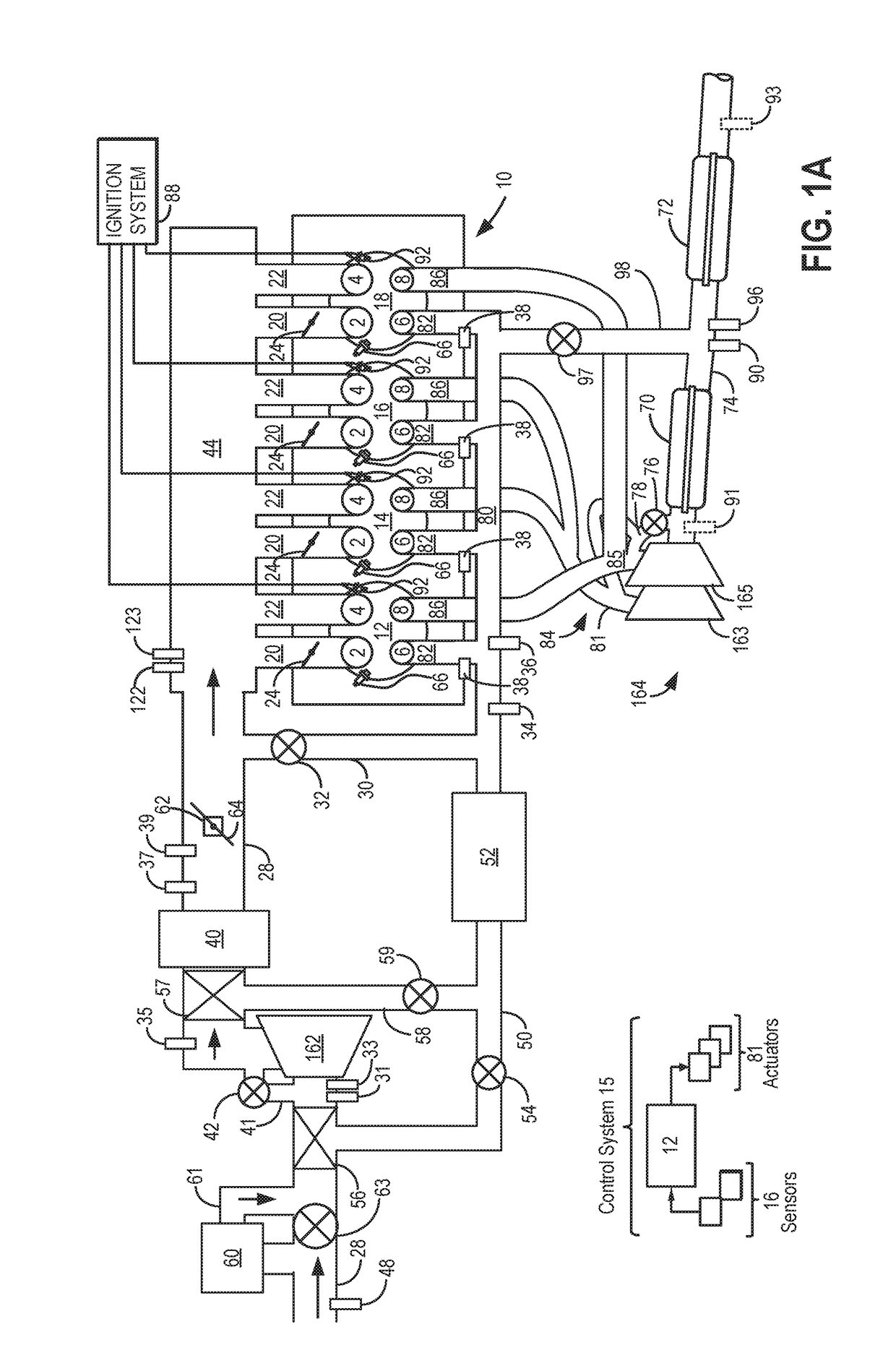
[0035]The following description relates to systems and methods for operating a split exhaust engine with blowthrough and exhaust gas recirculation (EGR) to an intake via a first exhaust manifold. As shown in FIG. 1A, the split exhaust engine may include a first exhaust manifold (referred to herein as a scavenge exhaust manifold) coupled exclusively to a scavenge exhaust valve of each cylinder. The scavenge manifold is coupled to the intake passage, upstream of a turbocharger compressor, via a first EGR passage including a first EGR valve (referred to herein as a BTCC valve). The split exhaust engine also include a second exhaust manifold (referred to herein as a blowdown exhaust manifold) coupled exclusively to a blowdown exhaust valve of each cylinder. The blowdown manifold is coupled to an exhaust passage of the engine, where the exhaust passage includes a turbocharger turbine and one or more emission control devices (which may include one or more catalysts). In some embodiments, ...


PUM


Abstract

Methods and systems are provided for operating a split exhaust engine system that provides blowthrough air and exhaust gas recirculation to an intake passage via a first exhaust manifold and exhaust gas to an exhaust passage via a second exhaust manifold. In one example, an air-fuel control method for the engine system may include flowing air from the intake manifold through a plurality of engine cylinders to a junction of the exhaust passage and a bypass passage in response to a condition, the junction positioned along the exhaust passage between first and second emission control devices. The method may further include flowing exhaust gas to the first emission control device while flowing the air to the junction.

Description

FIELD[0001]The present description relates generally to methods and systems for a split exhaust engine including exhaust gas recirculation.BACKGROUND / SUMMARY[0002]Engines may use boosting devices, such as turbochargers, to increase engine power density. However, engine knock may occur due to increased combustion temperatures. Knock is especially problematic under boosted conditions due to high charge temperatures. The inventors herein have recognized that utilizing an engine system with a split exhaust system, where a first exhaust manifold routes exhaust gas recirculation (EGR) to an intake of the engine, upstream of a compressor of the turbocharger, and where a second exhaust manifold routes exhaust to a turbine of the turbocharger in an exhaust of the engine, may decrease knock and increase engine efficiency. In such an engine system, each cylinder may include two intake valves and two exhaust valves, where a first set of cylinder exhaust valves (e.g., scavenge exhaust valves) ex...

Claims


Application Information

Patent Timeline
Patent Type & Authority Patents(United States)
IPC IPC(8): F02D41/02F02M35/10F02M35/104F02D13/06F01N3/021F02D41/00F02D13/02F02B37/00F02B29/08F01N13/10F01N3/10
CPCF02D41/029F01N3/021F01N3/101F01N13/107F02B29/08F02B37/00F02D13/0257F02D13/0261F02D13/06F02D41/005F02M35/104F02M35/10222F02D13/0234F02D13/0246F01N3/029F01N3/225F01N9/002F02D41/0007F02D41/025F02D41/1454F02D41/1475Y02T10/12
Inventor ULREY, JOSEPH NORMANLEWIS, DONALD
Owner FORD GLOBAL TECH LLC
Why Eureka
Try Eureka