
F-theta photolithographic lenses

a photolithographic lens and f-theta technology, applied in the field of optics, can solve the problems of high engraving speed, limited by materials and technology, and difficult to provide engraving lines with high-quality, and achieve the effect of high engraving speed and more efficien

Active Publication Date: 2018-12-25
HANS LASER TECH IND GRP CO LTD
View PDF9 Cites 0 Cited by
  • Summary
  • Abstract
  • Description
  • Claims
  • Application Information

AI Technical Summary

Benefits of technology

The patent describes an F-θ lens for laser engraving that can create high-quality engraved lines quickly. This lens uses a special structure called F-θ that allows for fine and deep engraved lines. Compared to other conventional F-θ lenses, it is much more efficient in engraving.

Problems solved by technology

As for the use of three F-θ lens for laser engraving, although the engraving speed is higher, limited by materials and technics, it is difficult to provide engraved lines with high-quality.

Method used


Image

  • F-theta photolithographic lenses
  • F-theta photolithographic lenses
  • F-theta photolithographic lenses

Examples


Embodiment Construction

[0017]Embodiments of the disclosure are described more fully hereinafter with reference to the accompanying drawings. Numerous specific details are described hereinafter in order to facilitate a thorough understanding of the present disclosure. The various embodiments of the disclosure may, however, be embodied in many different forms and should not be construed as limited to the specific embodiments set forth hereinafter, and people skilled in the art can make similar modifications without departing from the spirit of the present disclosure.

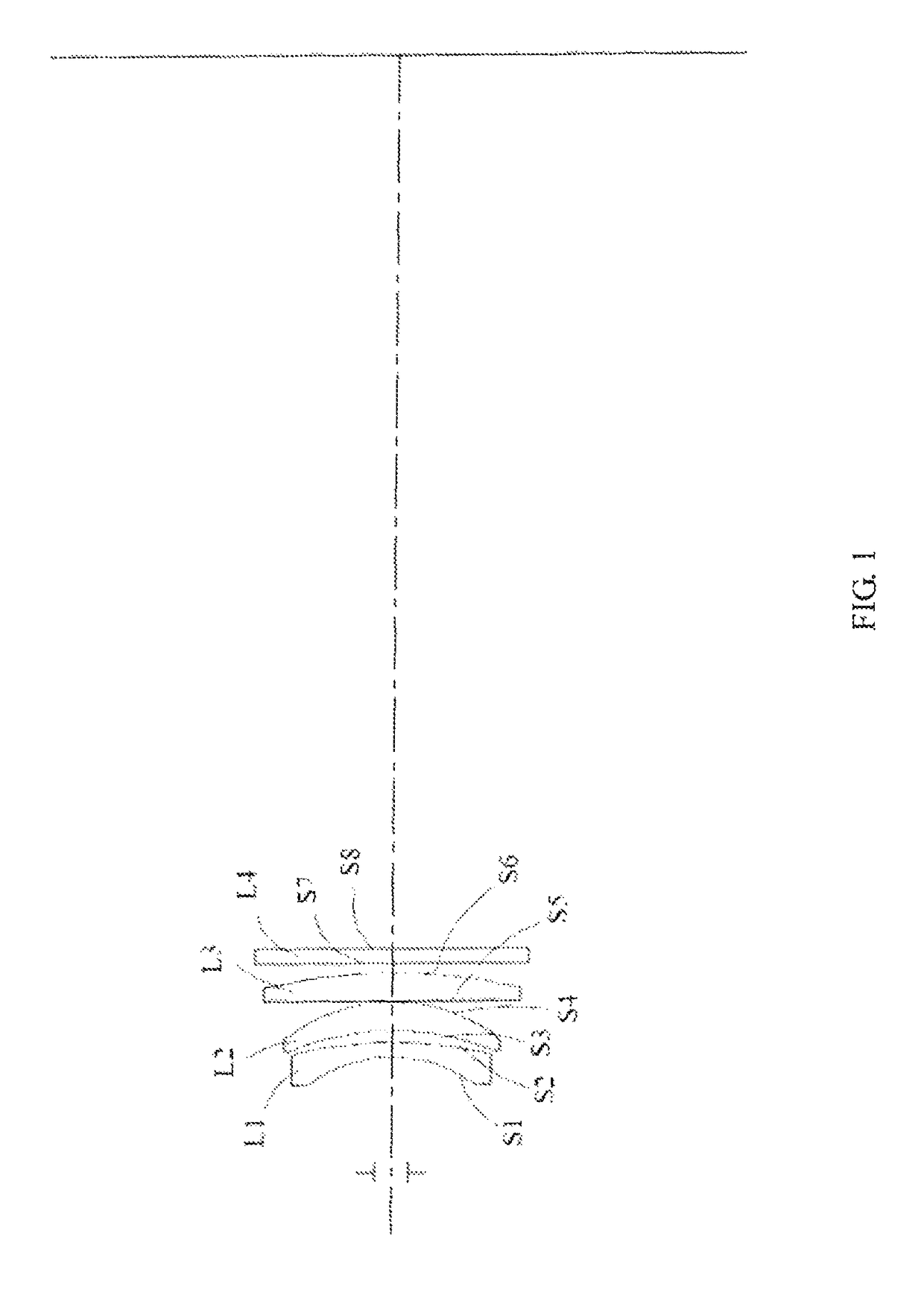
[0018]FIG. 1 is a schematic diagram of an F-θ lens for laser engraving according to an embodiment, for illustrative purposes, only portions related to implementation of the disclosure are shown.

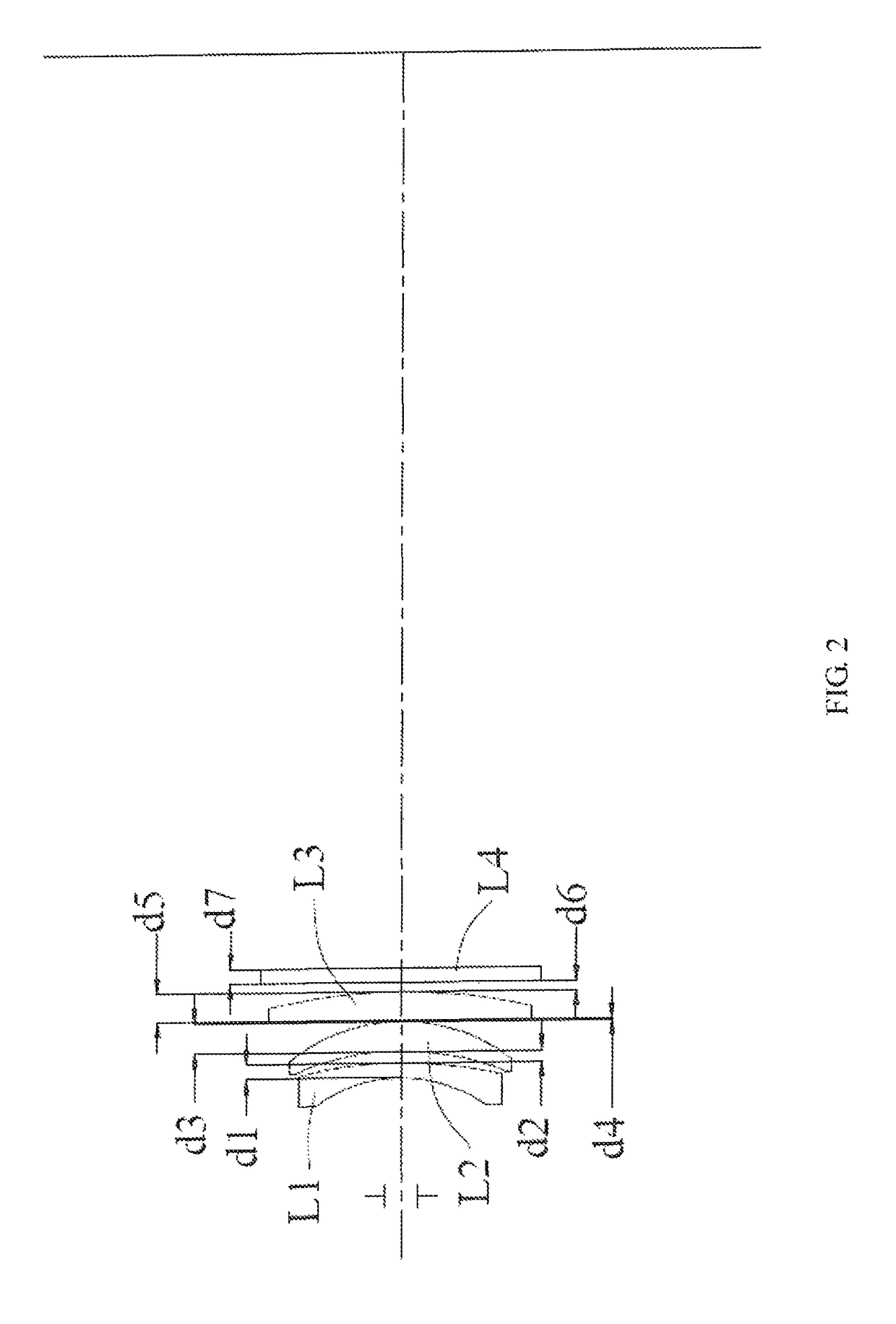
[0019]As shown in FIG. 1, the F-θ lens for laser engraving includes a first lens L1, a second lens L2, a third lens L3, and a fourth lens L4, which are coaxially arranged along a transmission direction of incident light.

[0020]In the F-θ lens for laser eng...


PUM

PropertyMeasurementUnit
thicknessesaaaaaaaaaa
thicknessaaaaaaaaaa

Abstract

An F-θ lens for laser engraving includes a first lens (L1), a second lens (L2), a third lens (L3), and a fourth lens (L4), which are coaxially arranged along a transmission direction of incident light; wherein the first lens (L1) is a meniscus lens, the second lens (L2) is a meniscus lens, the third lens (L3) is a plano-convex lens, and the fourth lens (L4) is a flat lens; wherein the first lens (L1) has a first surface (S1) and a second surface (S2), the second lens (L2) has a third surface (S3) and a fourth surface (S4), the third lens (L3) has a fifth surface (S5) and a sixth surface (S6), and the fourth lens (L4) has a seventh surface (S7) and an eighth surface (S8); the first surface (S1) to the eighth surface (S8) are sequentially arranged along the transmission direction of the incident light; wherein radii of curvature of the first surface (S1) to the eighth surface (S8) are −29 mm, −88 mm, −56 mm, −36 mm, ∞, −116 mm, ∞, and ∞, respectively; and center thicknesses (d1, d2, d3, d4) of the first lens (L1) to the fourth lens (L4) are 3 mm, 6 mm, 6 mm, and 3 mm, respectively.

Description

CROSS REFERENCE TO RELATED APPLICATIONS[0001]This application is a National Phase filing under 35 U.S.C. § 371 of PCT / CN2014 / 092428 filed on Nov. 28, 2014. The entire contents of the application is hereby incorporated by reference.FIELD OF THE INVENTION[0002]The present disclosure relates generally to the field of optics, and more specifically to an F-θ lens for laser engraving.BACKGROUND OF THE INVENTION[0003]With the development of electronic products such as mobile phones, personal computers and flat-panel TVs, the demand for production of panels on these products has also increased. In the production process of the panel, it is needed to mark the panel with laser, scribe and cut the panel, and in order to ensure that the panel meets the technical requirements of the product, when marking the panel with laser, it is to be ensured that the engraved lines are “fine” and “deep”. Therefore, requirements for the F-θ lens for laser engraving of a laser engraver are getting higher and h...

Claims


Application Information

Patent Timeline
Patent Type & Authority Patents(United States)
IPC IPC(8): G02B13/00B23K26/06B23K26/359
CPCG02B13/0005G02B13/0035B23K26/0648B23K26/359
Inventor SUN, BOLI, JIAYINGZHOU, CHAOMINGGAO, YUNFENG
Owner HANS LASER TECH IND GRP CO LTD
Learn More