
Wavelength-tunable III-V/Si hybrid optical transmitter

a hybrid optical transmitter and wavelength tunable technology, applied in the direction of optical elements, semiconductor lasers, instruments, etc., can solve the problems of complex active closed-loop feedback control system, limited tuning range, and inability to adjust so as to facilitate the adjustment of the frequency of the optical transmitter

Active Publication Date: 2018-12-25
ORACLE INT CORP
View PDF2 Cites 5 Cited by
  • Summary
  • Abstract
  • Description
  • Claims
  • Application Information

AI Technical Summary

Benefits of technology

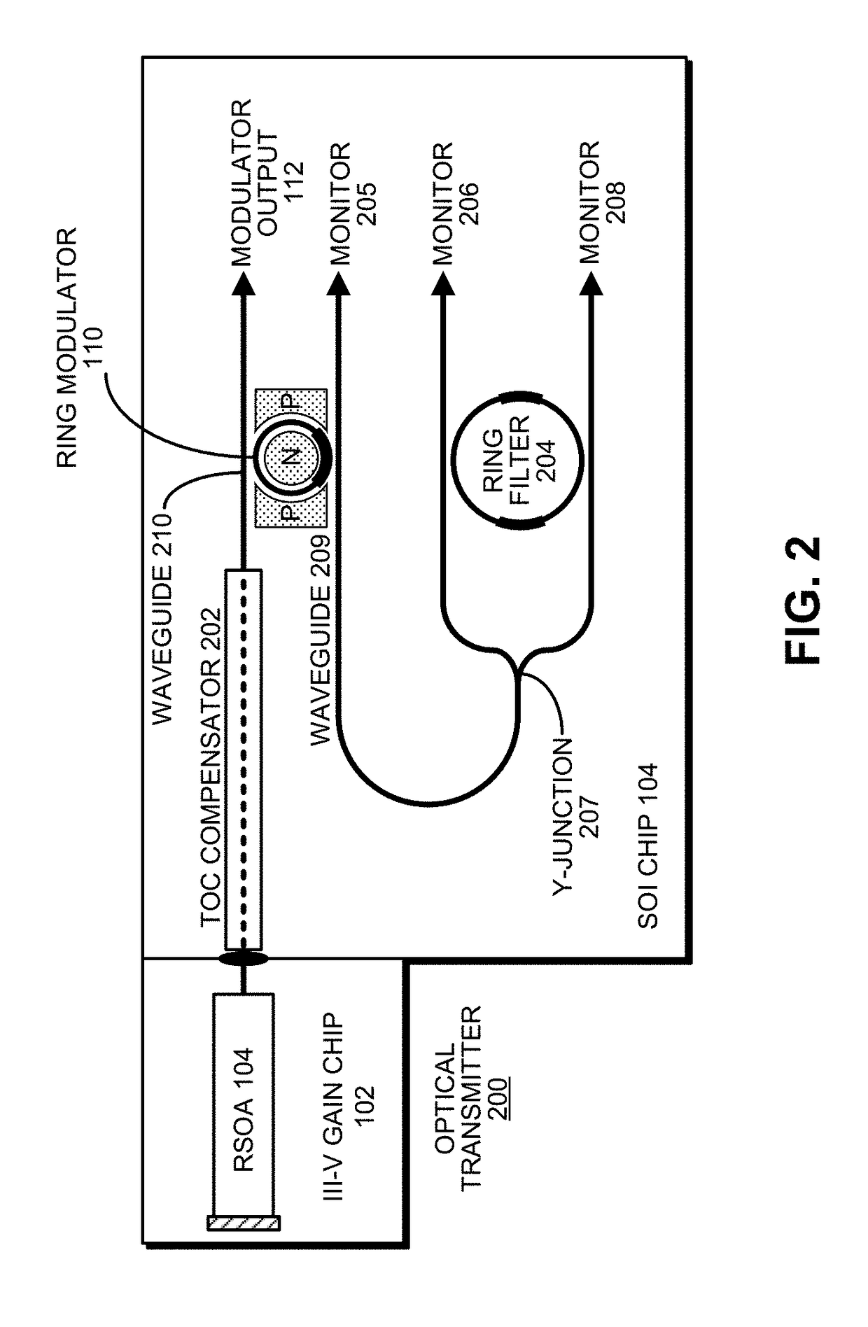
[0007]The disclosed embodiments provide an optical transmitter that includes a reflective semiconductor optical amplifier (RSOA), which is coupled to a first optical waveguide, which has an input end and an output end, wherein the input end is coupled to the RSOA, the output end provides a transmitter output for the optical transmitter, and a section of the first optical waveguide between the input end and the output end is optically coupled to a ring modulator that modulates an optical signal based on an electrical input signal. The optical transmitter also includes a passive ring filter optically coupled to the second optical waveguide. This passive ring filter is configured to provide a mirror that reflects light received from the second optical waveguide back toward the RSOA to form a lasing cavity, wherein the lasing cavity includes the RSOA, the first optical waveguide, the ring modulator, the second optical waveguide and the passive ring filter. Moreover, the ring modulator and the passive ring filter have different sizes, which causes a Vernier effect that provides a large wavelength tuning range for the lasing cavity in response to tuning the ring modulator and the passive ring filter.
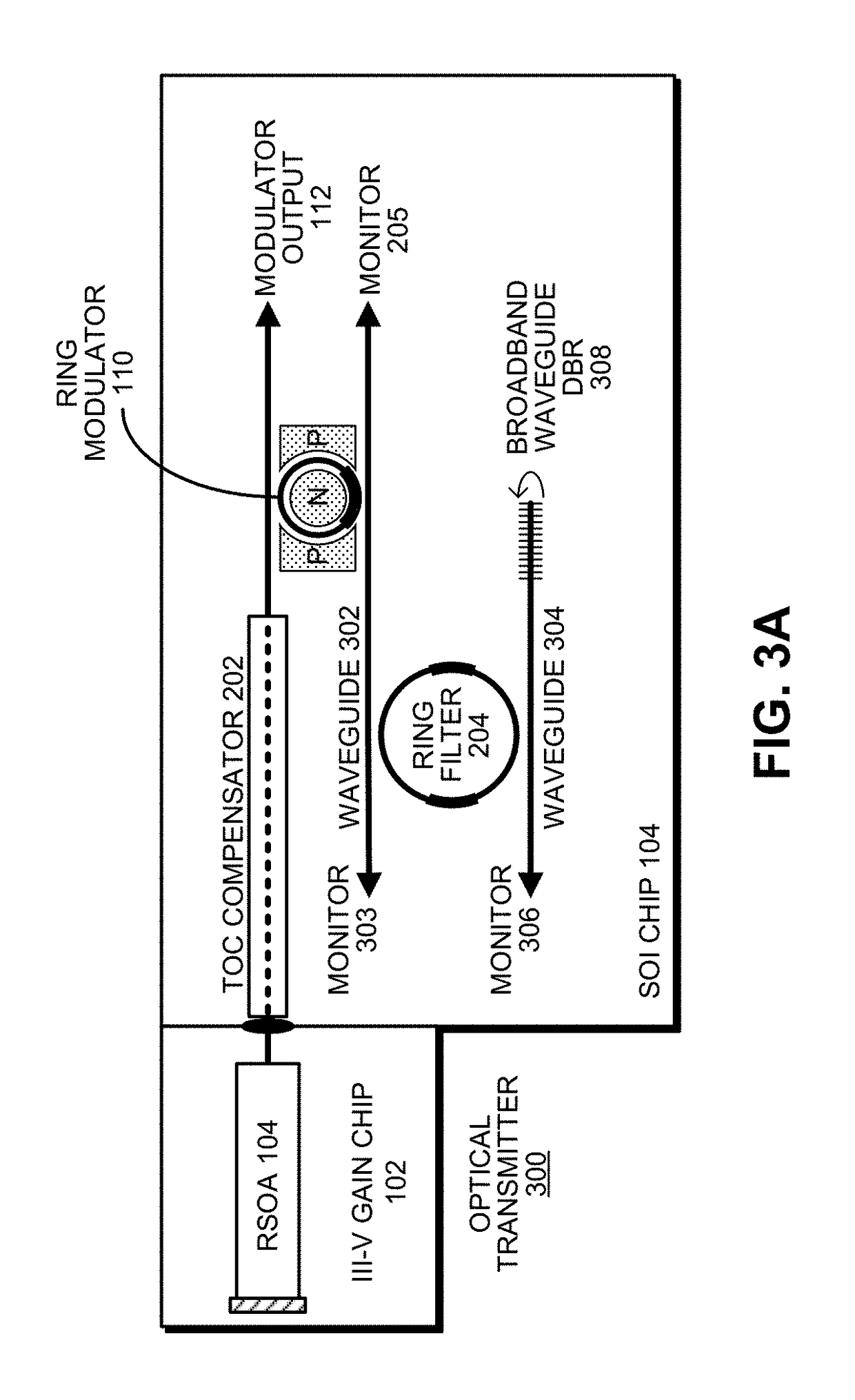
[0015]The disclosed embodiments also provide another optical transmitter that includes a reflective semiconductor optical amplifier (RSOA), which is coupled to a first optical waveguide, which has an input end and an output end, wherein the input end is coupled to the RSOA, the output end provides a transmitter output for the optical transmitter, and a section of the first optical waveguide between the input end and the output end is optically coupled to a ring modulator that modulates an optical signal based on an electrical input signal. The optical transmitter also includes an array of N narrow-band reflectors, wherein each narrow-band reflector has a different center wavelength, and a 1×N silicon-photonic switch, having an input port and N output ports, wherein each output port is coupled to a different narrow-band reflector in the array of N narrow-band reflectors. The optical transmitter additionally includes a second optical waveguide with a first end optically coupled to the ring modulator and a second end coupled to the input port of the 1×N silicon-photonic switch. Finally, the optical transmitter includes an adjustment mechanism that facilitates adjusting a frequency of the optical transmitter in discrete increments by selectively coupling the input port of the 1×N silicon-photonic switch to one of the N output ports. This causes the RSOA, the first optical waveguide, the ring modulator, the second optical waveguide and the 1×N silicon-photonic switch to form a lasing cavity with a narrow-band reflector coupled to the selected output port of the 1×N silicon-photonic switch, wherein the lasing cavity has a wavelength that is determined by the center wavelength of the selected narrow-band reflector.

Problems solved by technology

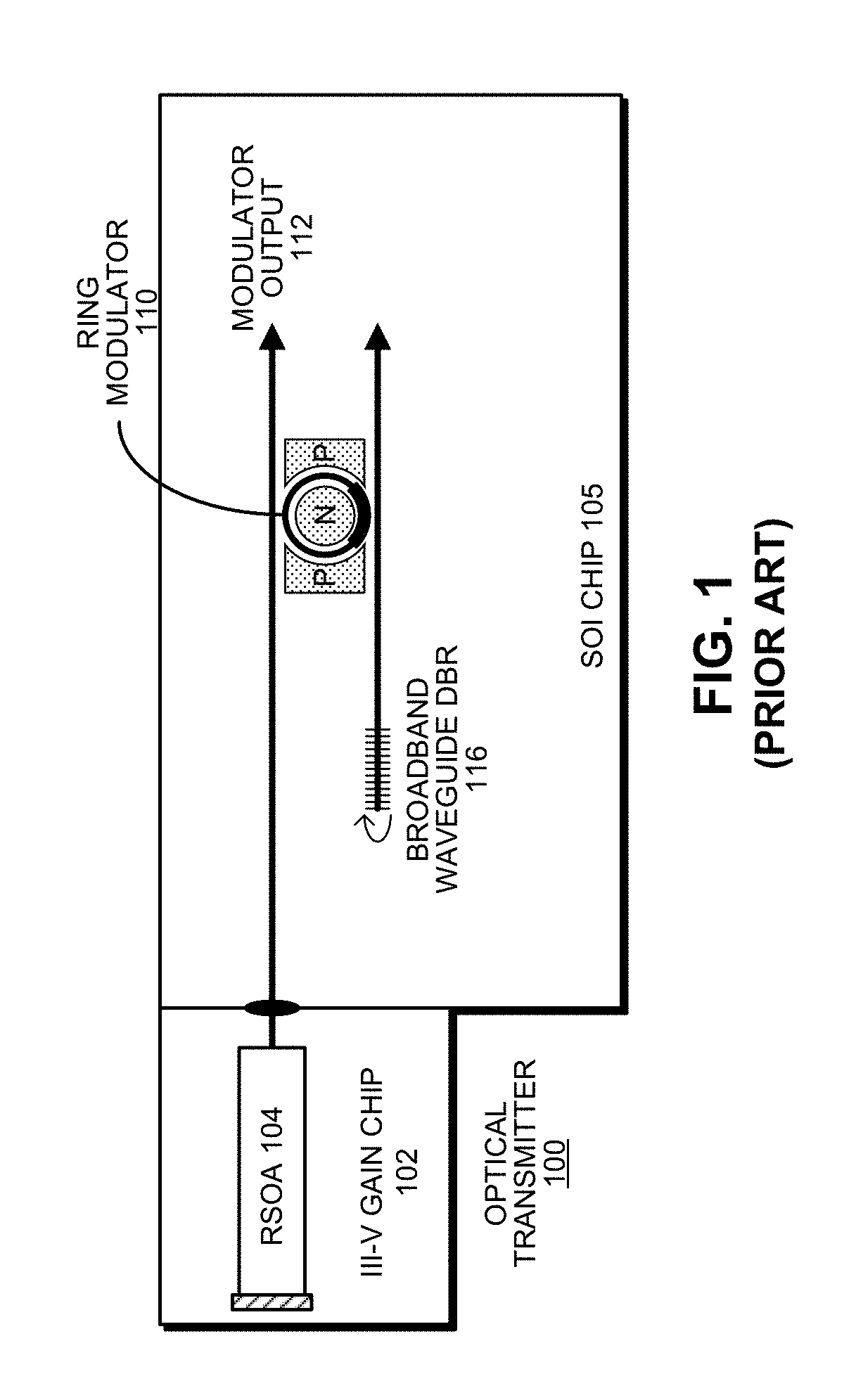
In spite of the advantages of the optical transmitter illustrated in FIG. 1, a number of challenges remain to make such an optical transmitter practical.
However, the tuning range is limited by the grating band reflector designed with a reflection band slightly smaller than the free spectral range (FSR) of the ring resonator.
In addition, the thermo-optic coefficient (TOC) difference between the III-V gain material and SOI silicon waveguides, can cause “walk-offs” between the hybrid cavity mode and the ring resonance.
Consequently, a complicated active closed-loop feedback control system is required for stable transmitter operation during ambient temperature changes.

Method used


Image

  • Wavelength-tunable III-V/Si hybrid optical transmitter
  • Wavelength-tunable III-V/Si hybrid optical transmitter
  • Wavelength-tunable III-V/Si hybrid optical transmitter

Examples


Embodiment Construction

[0023]The following description is presented to enable any person skilled in the art to make and use the present embodiments, and is provided in the context of a particular application and its requirements. Various modifications to the disclosed embodiments will be readily apparent to those skilled in the art, and the general principles defined herein may be applied to other embodiments and applications without departing from the spirit and scope of the present embodiments. Thus, the present embodiments are not limited to the embodiments shown, but are to be accorded the widest scope consistent with the principles and features disclosed herein.

[0024]The data structures and code described in this detailed description are typically stored on a computer-readable storage medium, which may be any device or medium that can store code and / or data for use by a computer system. The computer-readable storage medium includes, but is not limited to, volatile memory, non-volatile memory, magneti...


PUM

PropertyMeasurementUnit
sizesaaaaaaaaaa
wavelengthaaaaaaaaaa
lengthaaaaaaaaaa

Abstract

An optical transmitter includes a reflective semiconductor optical amplifier (RSOA) coupled to an input end of a first optical waveguide. An end of the first optical waveguide provides a transmitter output for the optical transmitter. Moreover, a section of the first optical waveguide between the input end and the output end is optically coupled to a ring modulator that modulates an optical signal based on an electrical input signal. A passive ring filter (or a 1×N silicon-photonic switch and a bank of band reflectors) is connected to provide a mirror that reflects light received from the second optical waveguide back toward the RSOA to form a lasing cavity. Moreover, the ring modulator and the passive ring filter have different sizes, which causes a Vernier effect that provides a large wavelength tuning range for the lasing cavity in response to tuning the ring modulator and the passive ring filter.

Description

GOVERNMENT LICENSE RIGHTS[0001]This invention was made with U.S. government support under Agreement No. HR0011-08-9-0001 awarded by DARPA. The U.S. government has certain rights in the invention.FIELD[0002]The disclosed embodiments relate to the design of a tunable optical transmitter. More specifically, the disclosed embodiments relate to the design of a wavelength-tunable hybrid III-V / Si optical transmitter.RELATED ART[0003]Silicon photonics is a promising new technology that can provide large communication bandwidth, low latency and low power consumption for inter-chip and intra-chip connections or optical links. In order to achieve low-latency, high-bandwidth optical connectivity, a number of optical components are required, including: optical transmitters, optical detectors, optical multiplexers, optical demultiplexers and lasers.[0004]A number of high-performance optical transmitters have recently been developed. For example, FIG. 1 illustrates the design of a III-V / Si hybrid ...

Claims


Application Information

Patent Timeline
Patent Type & Authority Patents(United States)
IPC IPC(8): G02F1/01H01S5/50G02B6/293H01S5/10H01S5/125H01S5/30H01S5/06G02B6/28
CPCG02F1/011G02B6/2808G02B6/29338H01S5/0612H01S5/125H01S5/3013H01S5/50H01S5/1071G02F2203/70G02F2203/15G02B6/4286G02B6/12004H01S5/1007H01S5/1032H01S5/142
Inventor ZHENG, XUEZHELUO, YINGYAO, JINKRISHNAMOORTHY, ASHOK V.
Owner ORACLE INT CORP
Learn More