
Micro electro mechanical system, vertical cavity surface emitting laser and preparation method thereof

A vertical cavity surface emission, MEMS technology, used in lasers, laser parts, semiconductor lasers, etc., can solve the problems of stress concentration, uneven force on the cantilever beam, affecting the wavelength tuning range, etc., to achieve uniform stress distribution, reduce Maximum stress, effect of increasing wavelength tuning range

Pending Publication Date: 2021-03-23
INST OF SEMICONDUCTORS - CHINESE ACAD OF SCI
View PDF10 Cites 0 Cited by
  • Summary
  • Abstract
  • Description
  • Claims
  • Application Information

AI Technical Summary

Problems solved by technology

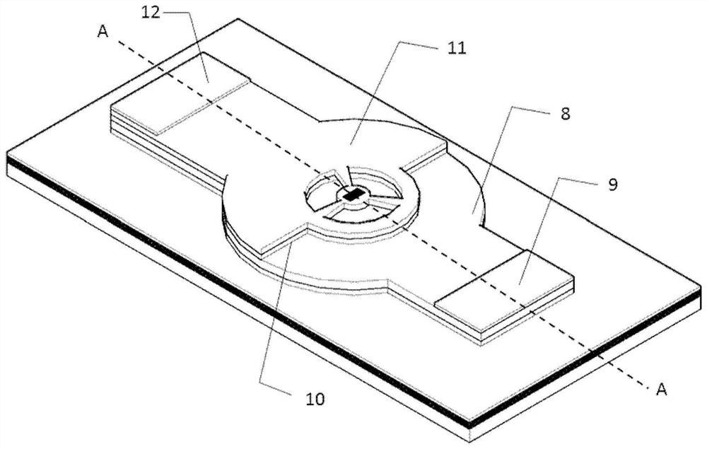
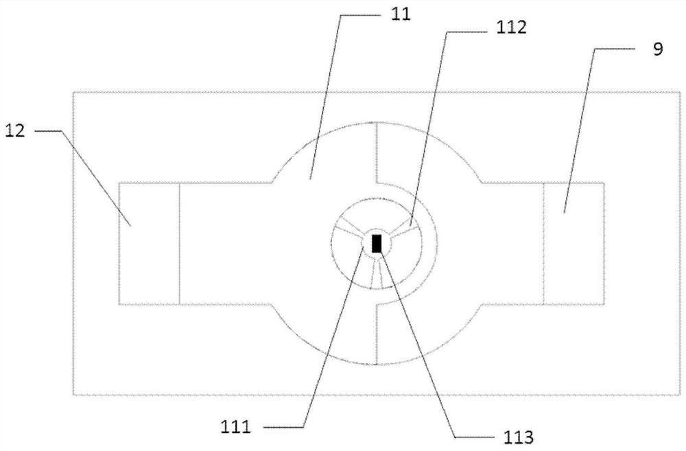
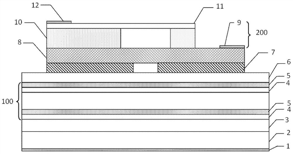
[0004] In order to solve the above-mentioned problems in the prior art, the present disclosure provides a microelectromechanical system structure for a vertical cavity surface emitting laser, a vertical cavity surface emitting laser and a preparation method thereof. The cantilever beam in the electromechanical system is not uniformly stressed, which is prone to stress concentration and affects the wavelength tuning range.

Method used


Image

  • Micro electro mechanical system, vertical cavity surface emitting laser and preparation method thereof
  • Micro electro mechanical system, vertical cavity surface emitting laser and preparation method thereof
  • Micro electro mechanical system, vertical cavity surface emitting laser and preparation method thereof

Examples


Embodiment Construction

[0023] Hereinafter, embodiments of the present disclosure will be described with reference to the drawings. It should be understood, however, that these descriptions are exemplary only, and are not intended to limit the scope of the present disclosure. In the following detailed description, for purposes of explanation, numerous specific details are set forth in order to provide a thorough understanding of the embodiments of the present disclosure. It may be evident, however, that one or more embodiments may be practiced without these specific details. Also, in the following description, descriptions of well-known structures and techniques are omitted to avoid unnecessarily obscuring the concepts of the present disclosure.

[0024] It will be understood that when an element such as a layer, film, region, or substrate is referred to as being "on" another element, it can be directly on the other element or intervening elements may also be present. Also, in the specification and...


PUM

PropertyMeasurementUnit
radiusaaaaaaaaaa
thicknessaaaaaaaaaa
radiusaaaaaaaaaa

Abstract

The disclosure provides a micro electro mechanical system for a vertical cavity surface emitting laser. The system comprises an injection electrode arranged at one end of the surface of an ohmic contact layer, a sacrificial layer arranged at the other end of the surface of the ohmic contact layer so as to be opposite to the injection electrode, an upper reflecting mirror layer arranged on the surface of the sacrificial layer, an a tuning electrode. A uniform fan blade cantilever structure is formed on the upper reflecting mirror layer, and the uniform fan blade cantilever structure comprises acircular reflecting mirror and a plurality of fan blade cantilevers; the plurality of fan blade cantilevers are spaced through air, and the sacrificial layer below the uniform fan blade cantilever structure is removed through corrosion, so that the uniform fan blade cantilever structure is suspended; and the tuning electrode is arranged on the surface of the upper reflecting mirror layer. The disclosure also provides a vertical cavity surface emitting laser and a preparation method thereof.

Description

technical field [0001] The disclosure relates to the technical field of semiconductor optoelectronic devices, in particular to a micro-electromechanical system, a vertical cavity surface emitting laser and a preparation method thereof. Background technique [0002] Vertical-cavity surface-emitting lasers are widely used in the field of optical communications. Combined with dense wavelength division multiplexing technology, high-capacity and high-efficiency signal transmission can be achieved. However, the emission wavelength of traditional vertical-cavity surface-emitting lasers is unchanged. If Directly integrating lasers with different wavelengths will not only cause system instability, but also increase production costs. Utilizing the tunable vertical cavity surface emitting laser based on the micro-electromechanical system, the deformation of the upper mirror can be pulled by the electrostatic force, which can realize the multi-wavelength output of a single light source ...

Claims


Application Information

Patent Timeline
Patent Type & Authority Applications(China)
IPC IPC(8): B81B7/02B81C1/00H01S5/10H01S5/183
CPCB81B7/02B81C1/0015H01S5/1096H01S5/18397H01S5/18361B81B2201/042B81B2203/0118
Inventor 吕家纲李伟刘素平马骁宇
Owner INST OF SEMICONDUCTORS - CHINESE ACAD OF SCI
Learn More