Optically triggered Q-switched photonic crystal laser and method of switching the same

Inactive Publication Date: 2006-10-26
CALIFORNIA INST OF TECH
View PDF8 Cites 1 Cited by
  • Summary
  • Abstract
  • Description
  • Claims
  • Application Information

AI Technical Summary

Benefits of technology

[0014] The primary advantage in the Q-switched photonic crystal laser implementation is that the bulk of the tuning is achieved by switching the laser emission between two different cavity modes. Some additional tuning is obtained by changing the cavity optical path length due to the rotating the molecular orientation of the liquid crystal. The tuning of the Q-switched laser is limited not by the birefringence of the infiltrated material, but rather by the difference in wavelengths of the cavity modes.
[0015] Besides an extremely large wavelength tuning range, anot

Problems solved by technology

The tuning of the Q-switched laser is limited not by the birefringence of the infi

Method used


Image

  • Optically triggered Q-switched photonic crystal laser and method of switching the same
  • Optically triggered Q-switched photonic crystal laser and method of switching the same
  • Optically triggered Q-switched photonic crystal laser and method of switching the same

Examples


Embodiment Construction

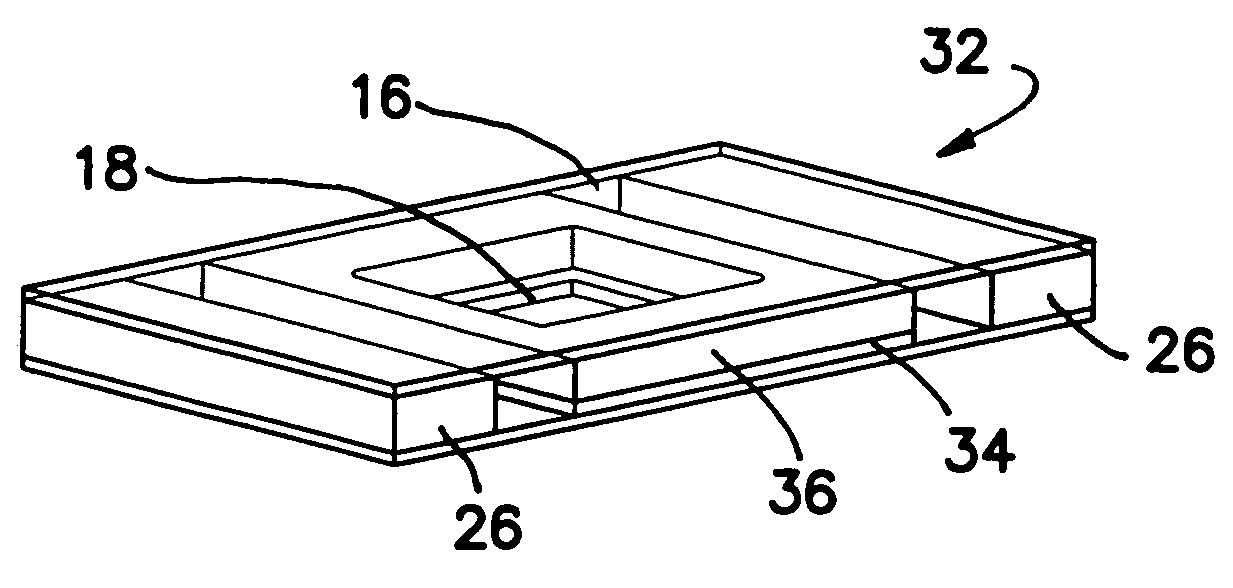
[0030] The illustrated embodiment involves the use of nonlinear liquids to create optically triggered quality-factor-switched (Q-switched) photonic crystal lasers 18. By infiltrating a photonic crystal laser 18 with an optically birefringent liquid crystal 34, and controlling the liquid crystal molecular orientation with a layer of photo addressable polymer 16, the lasing mode can be switched between X-polarized and Y-polarized dipole modes. The infiltrated liquid crystal 34 enables control over both polarization and wavelength emitted by the photonic crystal laser 18 and offers an example of an electromagnetically optimized device in which high optical fields and nonlinear material interact intimately.

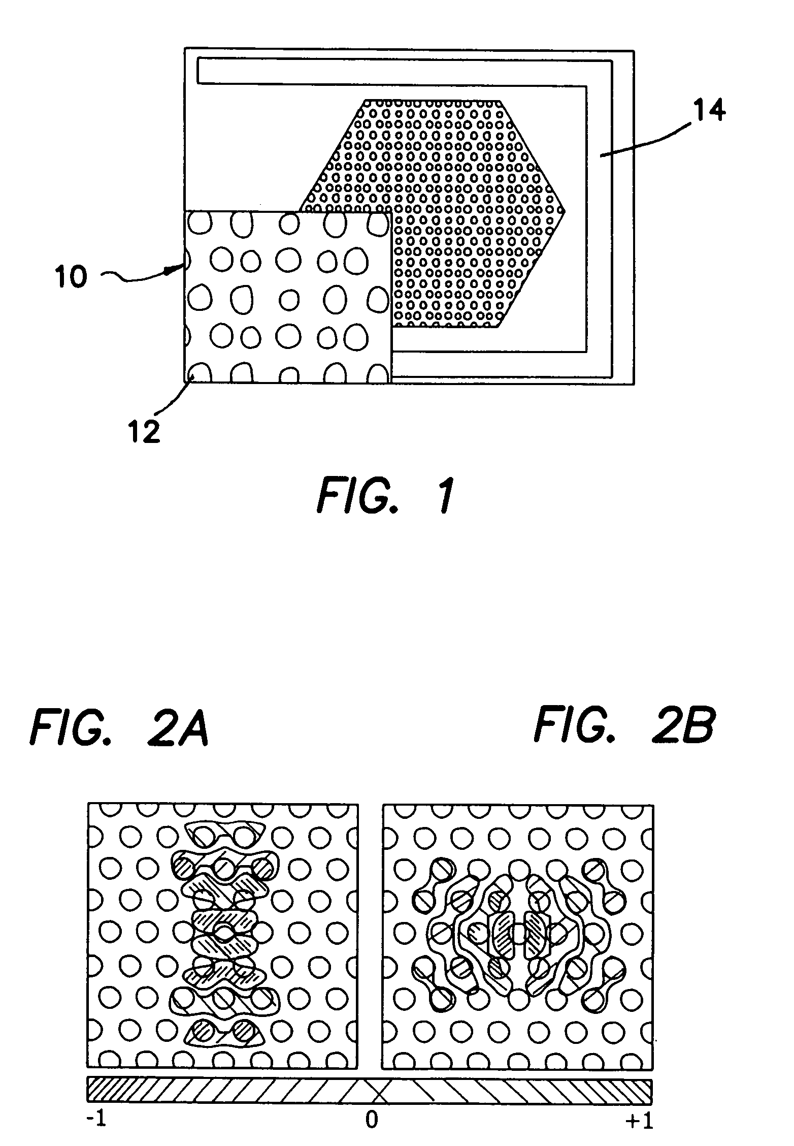
[0031] Microfabricated photonic crystal cavities 10 enable the efficient interaction of the confined lasing field with various optical materials. Although the light emission of the lasing mode is generated within the semiconductor material, it is possible to design high-Q optical cav...


PUM


Abstract

An improvement in a method of controlling lasing in a semiconductor laser fabricated in a photonic crystal laser having a plurality of holes into which a birefringent material with low refractive losses and low optical loses with controllable spatial refractive index orientation has been infiltrated comprises the step of rotating the molecular orientation or changing the physical orientation of the birefringent material infiltrated into the holes of the photonic crystal laser to switch cavity modes. The liquid crystal is aligned by use of an alignable photo addressable polymer layer adjacent to the liquid crystal. The cavity modes are optically switched within the laser without any requirement of external energy to maintain the lasing state of the laser, which allows its use as a memory element.

Description

RELATED APPLICATIONS [0001] The present application is related to U.S. Provisional Patent Application Ser. No. 60 / 647,088, filed on Jan. 26, 2005, which is incorporated herein by reference and to which priority is claimed pursuant to 35 USC 119.GOVERNMENT SUPPORT [0002] The present application was funded by DARPA pursuant to grant no. HR0011-04-1-0032. The U.S. Government has certain rights.BACKGROUND OF THE INVENTION [0003] 1. Field of the Invention [0004] The invention relates to the field of wavelength and polarization tunable photonic crystal (PC) lasers and methods of switching the same. [0005] 2. Description of the Prior Art [0006] Optics and fluidics have been historically integrated within systems that combine separate light sources, fluidic reservoirs and filters. Integration on a sub-millimeter scale has resulted in spectroscopic tools and liquid crystal (LC) displays. With the advent of photonic crystals (PCS) it has recently become possible to further integrate sources, ...

Claims


Application Information

Patent Timeline
IPC IPC(8): H01S3/098H01S3/11H01S3/10
CPCH01S5/0608H01S5/06236H01S5/3211H01S5/105H01S5/10H01S5/11
Inventor MAUNE, BRETT
Owner CALIFORNIA INST OF TECH
Why Eureka
Try Eureka