Multiplexer for controlling fluid in microfluidics chip and microfluidics chip assembly

a microfluidics chip and multi-layer technology, applied in the field of multi-layers, can solve the problems of significant manufacturing method or manufacturing cost of the micro valve, the life of the pneumatic valve itself is limitative, and the use limit of the pneumatic valve, so as to reduce the manufacturing cost

Active Publication Date: 2019-01-01
SOGANG UNIV RES FOUND
View PDF3 Cites 0 Cited by
  • Summary
  • Abstract
  • Description
  • Claims
  • Application Information

AI Technical Summary

Benefits of technology

[0009]The present invention provides a multiplexer and a microfluidics chip assembly including the same, which can exclude a separate membrane selectively interrupting a microchannel of a microfluidics chip and control a flow of fluids in the microchannel to solve various problems in use and manufacturing, such as a limit in life-span or a process of forming a membrane.
[0011]The present invention provides a multiplexer and a microfluidics chip assembly including the same, which can respective microchannels only with less solenoid valves than the microchannels without arranging a pneumatic valve and a solenoid valve for controlling the microchannels provided in the microfluidics chip one to one to implement simplification of a manufacturing process and saving of manufacturing cost through the simplification of the manufacturing process.
[0014]Selective interruption of the microchannel is implemented by using not a separate thin film but only the pneumatic pressure, and as a result, a complicated process for generating a membrane is omitted, thereby reducing manufacturing cost.
[0015]Further, when air pressure is provided to any one side of the first and second pneumatic channels, pressure leaks to the other side and the pneumatic pressure is provided to both the first and second pneumatic channels to control the fluid in the microchannel of the microfluidics chip, and as a result, an external device (e.g., a solenoid valve) for providing the pressure need not be disposed to correspond to the microchannel one to one and the manufacturing cost can be reduced and the number of complicated external devices can be minimized, thereby enabling a high-density screening test.
[0022]In a microfluidics chip in the related art, a separate thin member is used for selective interruption of a microchannel, and as a result, a complicated membrane generation process is added and the membrane is limited in life-span in a thin synthetic resin form and the membrane may directly contact a drug in the microchannel in actual use. However, in the case of a multiplexer and a microfluidics chip assembly adopting the same, since only pneumatic pressure may can serve as a valve that controls a fluid in the microchannel without using the membrane, and as a result, a complicated process is omitted, thereby reducing manufacturing cost.
[0023]Further, in the case of the multiplexer and the microfluidics chip assembly adopting the same, only when the pneumatic pressure is applied to both first and second pneumatic channels connected with the microchannels or the pneumatic pressure is provided to any one of the first and second pneumatic channels and the other side is closed, the pneumatic pressure can serve as an opened valve and when air pressure is provided to any one side of the first and second pneumatic channels, the air pressure serves as a closed valve to cause the pressure to leak to the other side, and as a result, a solenoid valve need not be disposed in the microchannel one to one, therefore, the manufacturing cost can be reduced and the number of complicated external devices can be minimized, thereby enabling a high-density sorting inspection.

Problems solved by technology

However, when the thin polymer membrane is used as the pneumatic valve, a life-span of the pneumatic valve itself is limitative and the pneumatic valve has a limit in use due to direct contact with fluids in a channel, and the like.
Further, as the pneumatic valve selectively interrupting the channel, that is, the membrane needs to the channel one to one and a solenoid valve generating a pneumatic pressure needs to be connected to each channel, and the like, a manufacturing method or manufacturing cost of the micro valve is significant and controlling the flow of the fluids is significantly complicated because the channel needs to be controlled one to one.

Method used


Image

  • Multiplexer for controlling fluid in microfluidics chip and microfluidics chip assembly
  • Multiplexer for controlling fluid in microfluidics chip and microfluidics chip assembly
  • Multiplexer for controlling fluid in microfluidics chip and microfluidics chip assembly

Examples


Embodiment Construction

[0028]Hereinafter, exemplary embodiments of the present invention will be described in detail with reference to the accompanying drawings, but the present invention is not limited or restricted to the exemplary embodiments. For reference, in the description, like reference numerals substantially refer to like elements, which may be described by citing contents disclosed in other drawings under such a rule and contents determined to be apparent to those skilled in the art or repeated may be omitted.

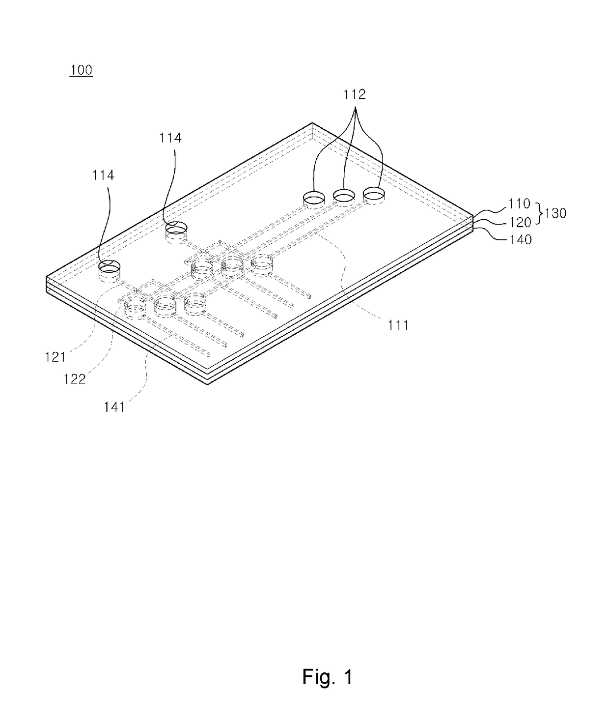
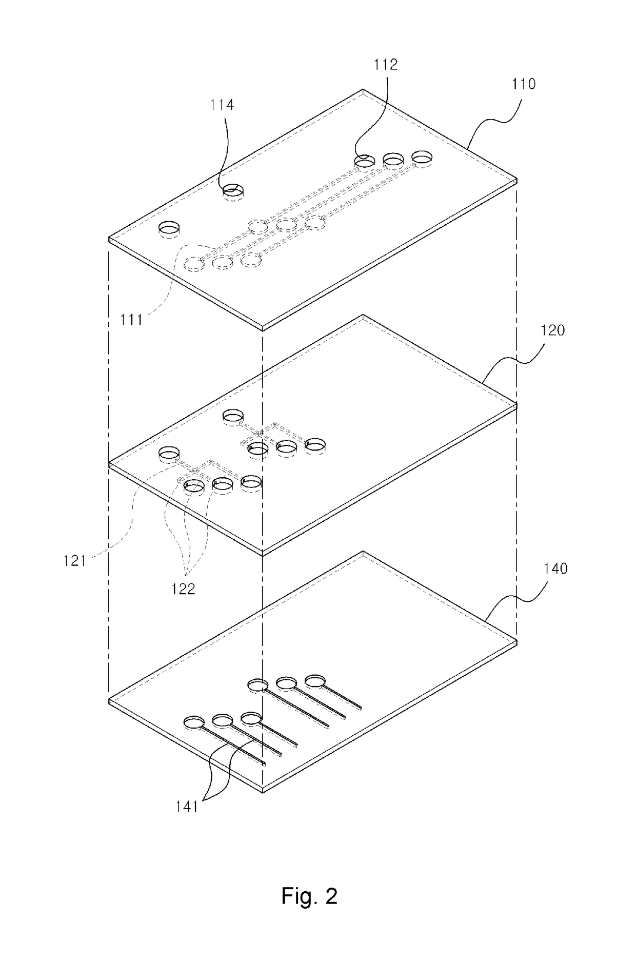
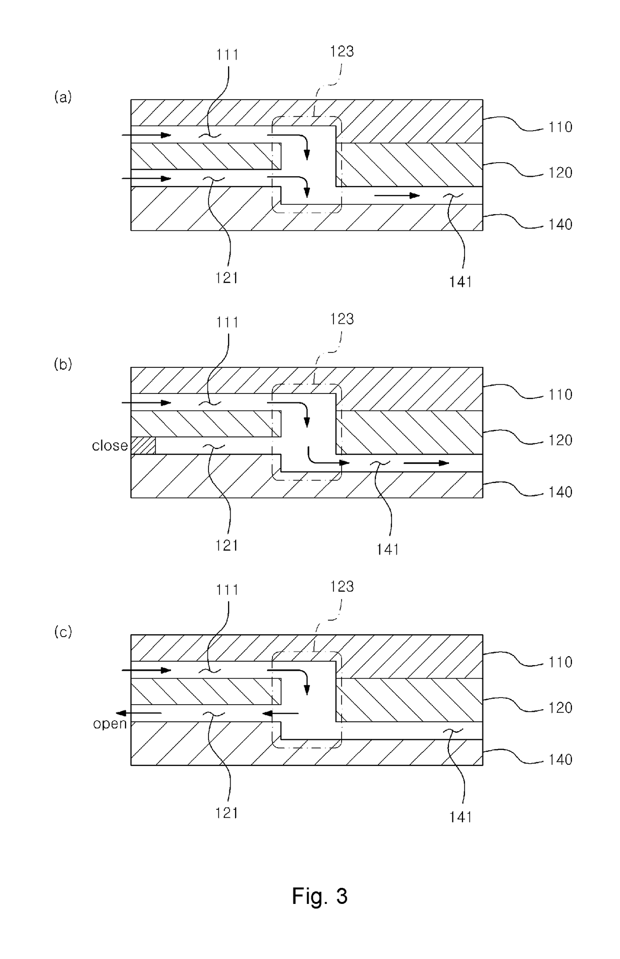
[0029]FIG. 1 is a perspective view of a microfluidics chip assembly according to an exemplary embodiment of the present invention. FIG. 2 is an exploded perspective view of the microfluidics chip assembly and FIG. 3 is a schematic structural diagram of a pneumatic channel and a microchannel for describing that air is selectively injected into the microchannel of a microfluidics chip by using a multiplexer.

[0030]Referring to FIGS. 1 to 3, the microfluidics chip assembly 100 according to the...


PUM

PropertyMeasurementUnit
pneumatic pressureaaaaaaaaaa
pressureaaaaaaaaaa
concentrationaaaaaaaaaa

Abstract

A multiplexer for controlling a fluid in a microchannel by controlling pneumatic pressure in the microchannel in a microfluidics chip includes: a first pneumatic channel; and a second pneumatic channel forming a cross point which is in communication with the first pneumatic channel, wherein the cross point is in communication with the microchannel of the microfluidics chip, and predetermined pneumatic pressure is provided to the microchannel by using a combination of providing of the pneumatic pressure to the first and second pneumatic channels, channel closing, or channel opening.

Description

CROSS-REFERENCE TO RELATED APPLICATION[0001]This application claims the benefit of Korean Patent Application No. 10-2016-0045560, filed on Apr. 14, 2016 in the Korean Intellectual Property Office, the disclosure of which is incorporated herein by reference.BACKGROUND OF THE INVENTION[0002]1. Field of the Invention[0003]The present invention relates to a multiplexer capable of controlling a fluid in a microchannel of a microfluidics chip and a microfluidics chip assembly including the same.[0004]2. Description of the Related Art[0005]A microfluidics chip may be called Lab-on-a-chip (LOC) and can analyze a profile in which while a small quality of materials to be analyzed flow, the materials react with various biomolecules or sensors aggregated in a chip. In recent years, application fields of the microfluidics chip have been widened primarily to separation, synthesis, quantitative analysis, and the like of an analyzed material.[0006]Meanwhile, as a method for controlling a flow of fl...

Claims


Application Information

Patent Timeline
Patent Type & Authority Patents(United States)
IPC IPC(8): B01L3/00F04B19/00G01N3/12B29C45/40
CPCB01L3/502715B01L2300/0816B01L2300/0861B01L2300/0864B01L2300/0867B01L2400/0666B01L2300/0887B01L2300/14B01L2400/0475B01L2400/0487B01L2300/0874
Inventor CHUNG, BONG GEUNKIM, TAE HYEONLEE, JONG MIN
Owner SOGANG UNIV RES FOUND
Why Eureka
Try Eureka