Safe valve for high pressure regulator

a high-pressure regulator and safe technology, applied in valve housings, fluid pressure control, instruments, etc., can solve the problems of increased reduced workability, complicated pipes connected to each valve, etc., to reduce improve workability, and minimize the effect of volume and weight of products

Active Publication Date: 2019-01-01
MOTONIC
View PDF17 Cites 5 Cited by
  • Summary
  • Abstract
  • Description
  • Claims
  • Application Information

AI Technical Summary

Benefits of technology

[0014]The object of the present invention is to solve the problems as mentioned above, and to provide the safe valve for the high pressure regulator, which is applied to a high pressure regulator for decompressing high pressure of the fuel into preset outlet pressure, thereby integrally providing functions to relieve the overpressure and discharge the fuel.
[0015]Another object of the present invention is to provide the safe valve for the high pressure regulator, for preventing the components from being completely separated during separation work from the high pressure regulator.
[0016]Still another object of the present invention is to provide the safe valve for the high pressure regulator, which can be easily reassembled after the separation from the high pressure regulator.
[0019]Further, according to the present invention, an integrated safe valve is applied, thus volume and weight of a product are minimized and pipes connected to the safe valve are simplified, so that workability is improved upon assembly work.
[0020]In addition, according to the present invention, a separation preventing pin is coupled to one side of the guide body to prevent the discharging pipe from being completely separated from the guide body, so that the discharging pipe is easily reassembled after separated from the high pressure regulator and reliability of a product is secured after reassembled.

Problems solved by technology

However, related arts have problems in that volume and weight of a product are increased, pipes connected to each valve are complicated, and workability is decreased upon assembling work, because an overpressure relief valve and a fuel discharging valve, which perform functions similar to each other, are separately installed at a high pressure regulator.
Accordingly, the high pressure regulator according to the related art has problems in that a mounting space is increased and managing points are increased upon vehicular maintenance and management work.
To solve the problems mentioned above, an integrated valve for integrating the overpressure relief valve and the fuel discharging valve is applied, however, the integrated valve has problems in that components of the integrated valve may be missed because the components are completely separated when the separation process is carried out for the fuel discharge function or reliability is degraded in the reassembling work.

Method used


Image

  • Safe valve for high pressure regulator
  • Safe valve for high pressure regulator
  • Safe valve for high pressure regulator

Examples


Embodiment Construction

[0025]A safe valve for a high pressure regulator according to a preferable embodiment of the present invention will be described in detail with reference to the accompanying drawings.

[0026]First, referring to FIGS. 1 to 3 according to a preferable embodiment of the present invention, the configuration of a high pressure regulator to which a safe valve is applied will be described.

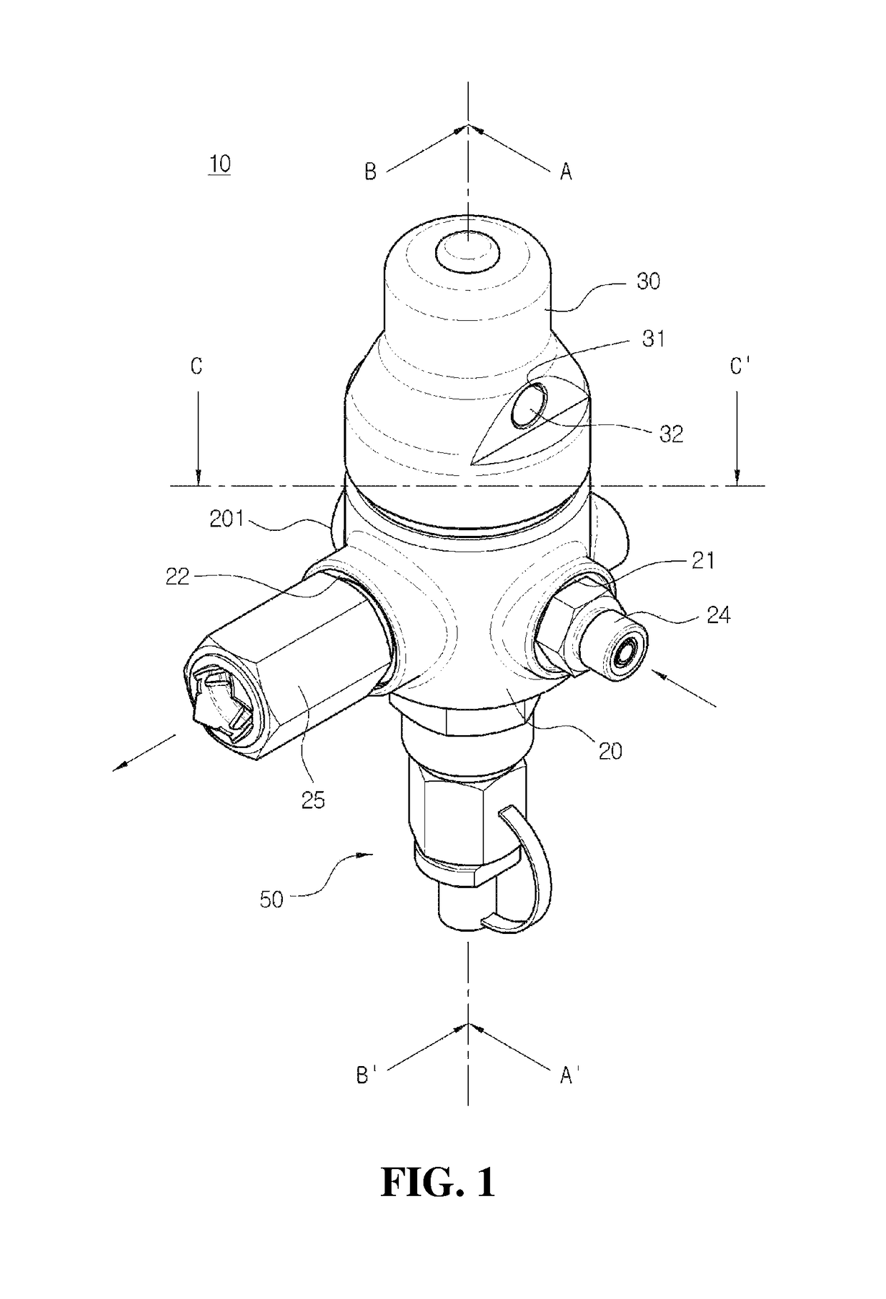
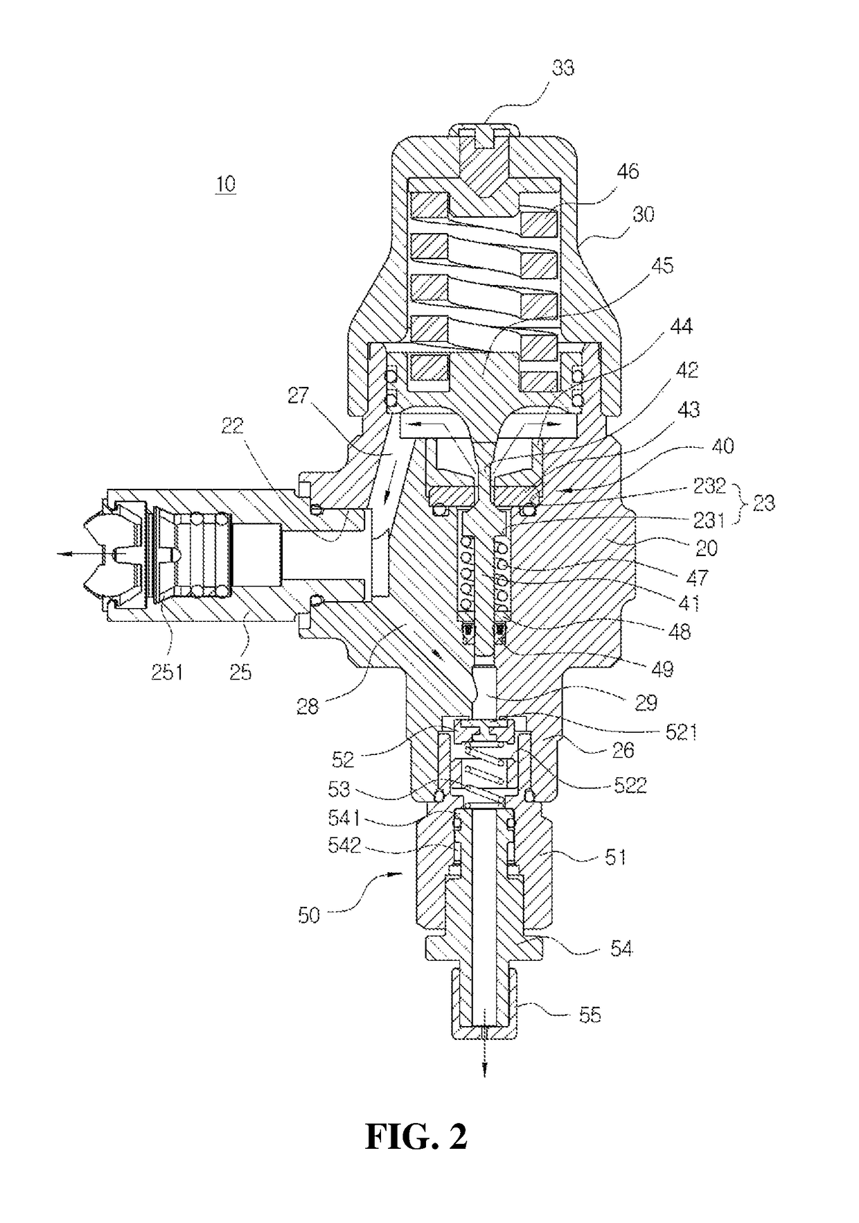
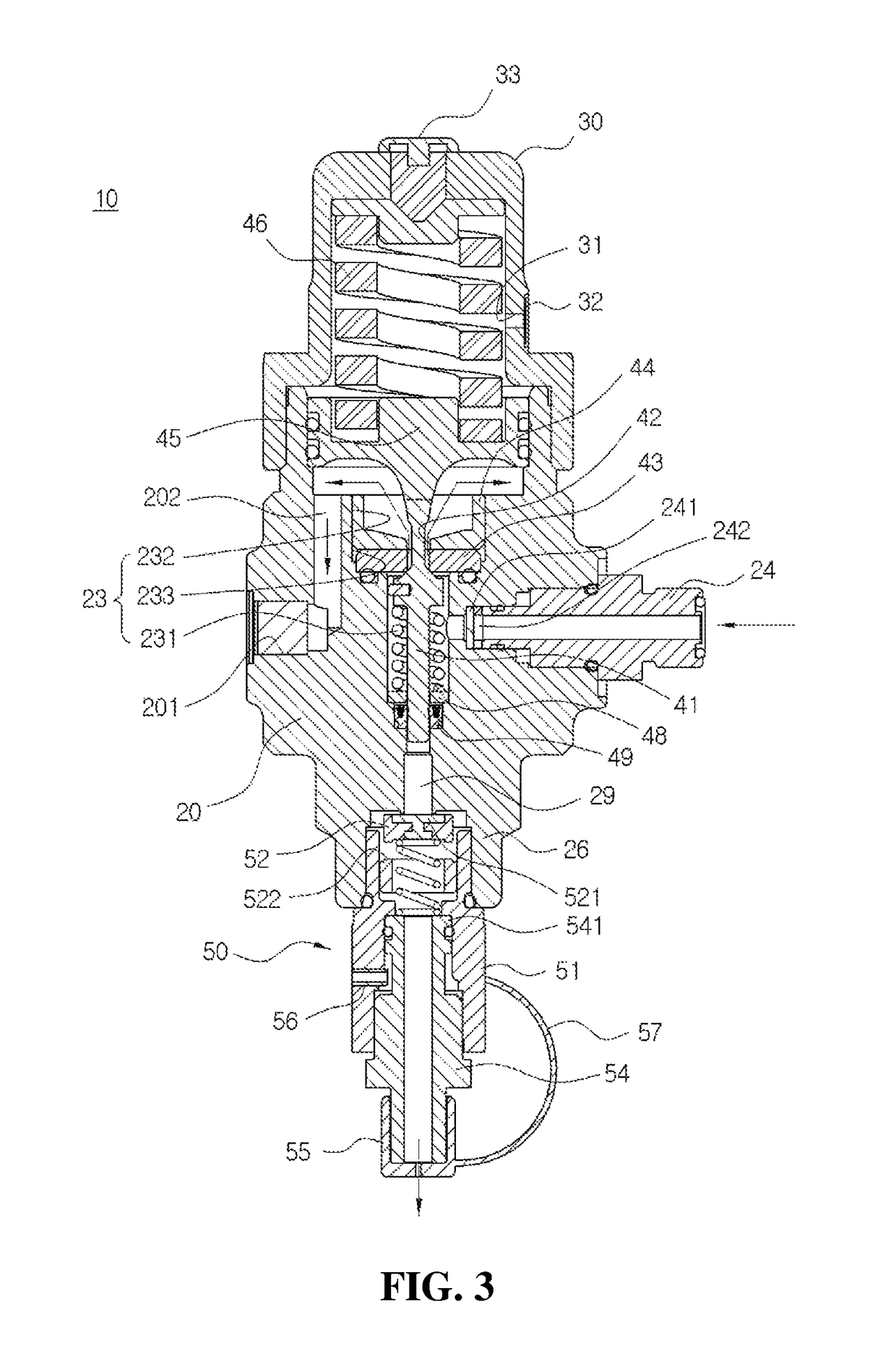
[0027]FIG. 1 is a perspective view showing the high pressure regulator to which the safe valve is applied according to the preferable embodiment of the present application, FIG. 2 is a sectional view taken along line A-A′ of FIG. 1, and FIG. 3 is a sectional view taken along line B-B′ of FIG. 1.

[0028]Hereinafter, the term indicating a direction such as “left”, “right”, “front”, “rear”, “upper” and “lower” is defined to indicate each direction, respectively, on the basis of the state shown in the drawings.

[0029]Although the safe valve, which is applied to a hydrogen FCEV, for the high pressure regulator is d...


PUM

PropertyMeasurementUnit
pressureaaaaaaaaaa
elastic forceaaaaaaaaaa
heightaaaaaaaaaa

Abstract

The present invention relates to a safe valve for a high pressure regulator, which includes: a guide body coupled to a valve port prepared at a body of a high pressure regulator; a valve body couple to an upper end part of the guide body to open the valve port when the overpressure occurs in a state that the valve port is closed; a lower spring installed inside the valve body for providing elastic force to the valve body; and a discharging pipe couple to a lower part of the guide body for discharging the fuel upon an opening operation of the valve body, wherein a function for a relief valve to relieve the overpressure by discharging the fuel when the overpressure is generated inside the high pressure regulator and a function for a purge valve separated from the body to discharge fuel inside the high pressure regulator are integrally provided.

Description

BACKGROUND OF THE INVENTION1. Field of the Invention[0001]The present invention relates to a safe valve for a high pressure regulator, and more specifically, to a safe valve for a high pressure regulator, which is applied to the high pressure regulator decompressing high pressure of fuel into preset outlet pressure, thereby relieving overpressure and discharging the fuel.2. Description of the Related Art[0002]In general, a hydrogen fuel cell electric vehicle (FCEV) uses electric energy as power source at a stack by using oxygen and hydrogen and electrochemically generating electricity to directly convert chemical energy of fuel into electric energy.[0003]The hydrogen FCEV is an ideal technology having high efficiency with no contaminants because it continuously generates power regardless of a cell capacity by supplying fuel and air from the outside. Accordingly, various development efforts are in progress for the hydrogen FCEV.[0004]The hydrogen FCEV provides hydrogen fuel from a fu...

Claims


Application Information

Patent Timeline
Patent Type & Authority Patents(United States)
IPC IPC(8): F16K31/12F16K17/04G05D16/04F16K17/00H01M8/04089G05D16/06
CPCF16K17/048F16K17/00G05D16/04H01M8/04104G05D16/0663Y10T137/7826Y10T137/7794G05D16/107Y02E60/50F16K17/04F16K27/02H01M8/04089H01M8/04201H01M2250/20Y02T90/40
Inventor LEE, SANG RYULJEON, WAN JAEGI, SUNG KYUNGJANG, SUNG GILJEONG, YUN HO
Owner MOTONIC
Why Eureka
Try Eureka