Gas filling method

a gas filling and gas technology, applied in the direction of electrochemical generators, container discharging methods, packaged goods types, etc., can solve the problems of inaccurateness, rapid increase in pressure and temperature of connected tanks, etc., and achieve the effect of reliable determination of initial pressure and prolonged acquisition time of initial pressur

Active Publication Date: 2019-01-01
HONDA MOTOR CO LTD
View PDF12 Cites 3 Cited by
  • Summary
  • Abstract
  • Description
  • Claims
  • Application Information

AI Technical Summary

Benefits of technology

[0010]As described above, the pre-shot method involves transferring a certain amount of hydrogen gas depending on the degree of pressurization of the station piping 101 before opening the flow control valve 103. Further, the station side can not determine the accurate capacity of the tank 110 immediately after connecting the filling nozzle 102 to the receptacle 112. Consequently, a predetermined amount of hydrogen gas will be transferred into the tank 110 regardless of its capacity when the pre-shot method is used. Therefore, the pre-shot method may induce rapid increase in the pressure and temperature of a connected tank if that tank has a capacity excessively smaller than commonly expected.

Problems solved by technology

Therefore, the pre-shot method may induce rapid increase in the pressure and temperature of a connected tank if that tank has a capacity excessively smaller than commonly expected.
Therefore, it is not accurate.

Method used


Image

  • Gas filling method
  • Gas filling method
  • Gas filling method

Examples


first embodiment

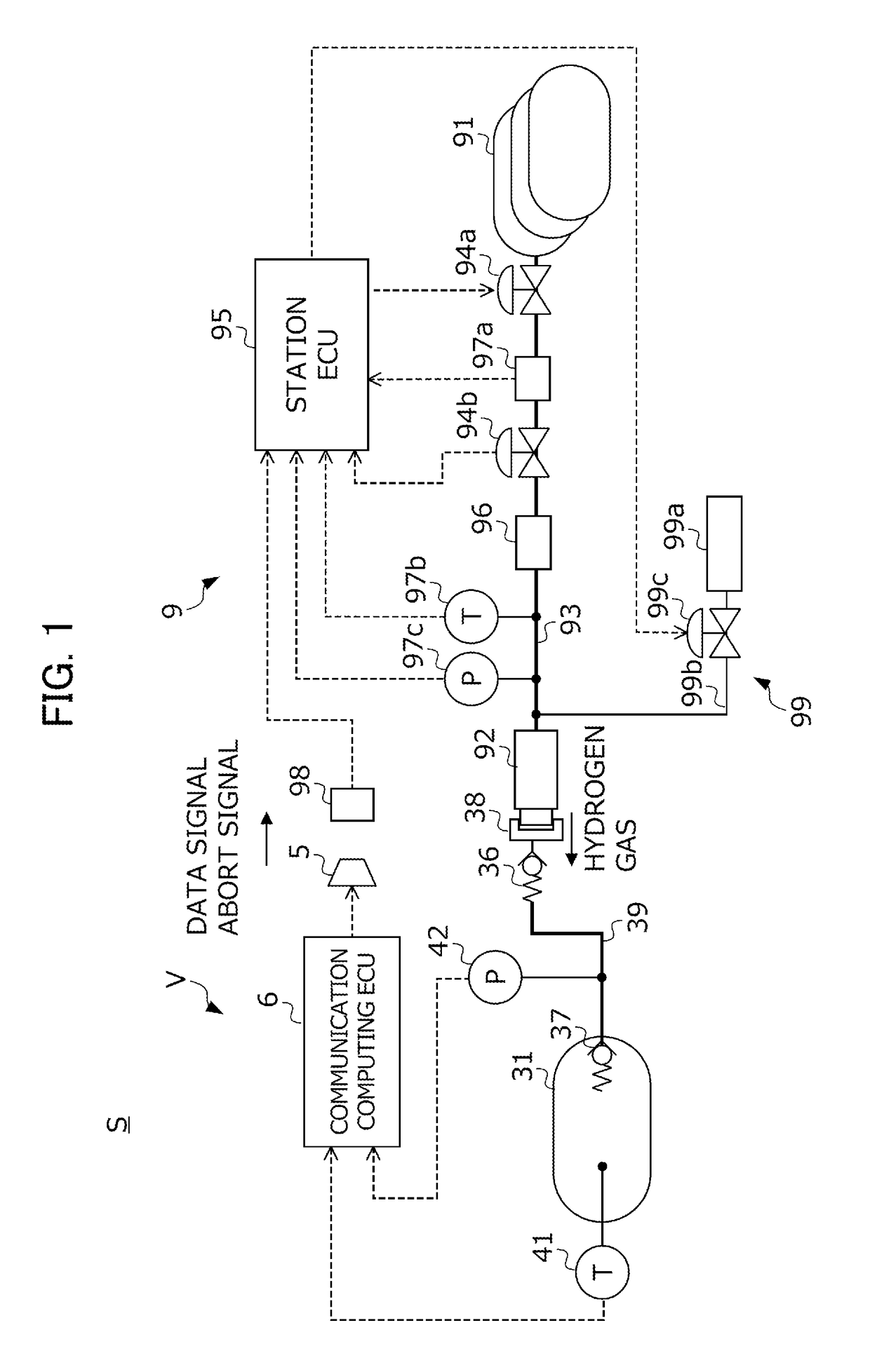
[0041]Below, the present invention will be described with reference to the figures. FIG. 1 shows the configuration of a hydrogen filling system S in which the hydrogen gas filling method according to this embodiment is used. The hydrogen filling system S includes the combination of a fuel cell vehicle V which runs on hydrogen gas as a fuel gas and a hydrogen station 9 as a supply system which supplies hydrogen gas to a hydrogen tank of the vehicles V. Below, the configuration of the hydrogen station 9 will first be described, and the configuration of the vehicle V will then be described.

[0042]The hydrogen station 9 includes a pressure accumulator 91 in which a high-pressure hydrogen gas to be supplied to the vehicle V is stored, a station piping 93 extending from the pressure accumulator 91 to a filling nozzle 92 for discharging hydrogen gas, a cutoff valve 94a and a flow control valve 94b provided in the station piping 93, a venting device 99 for handling hydrogen gas accumulating ...

second embodiment

[0087]The hydrogen gas filling method according to the present invention is described above, but the present invention shall not be limited to this. Details in the configuration may appropriately be altered without departing the scope of the present invention.

[0088]

[0089]Next, a third embodiment of the present invention will be described with reference to the figures. Note that illustrations and descriptions for those shared with the first embodiment are omitted when this embodiment is described below.

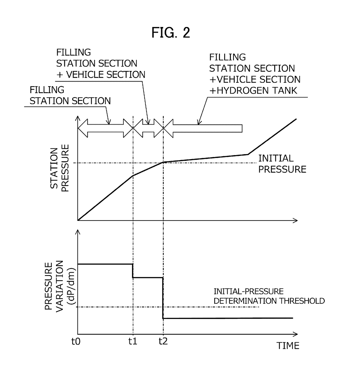
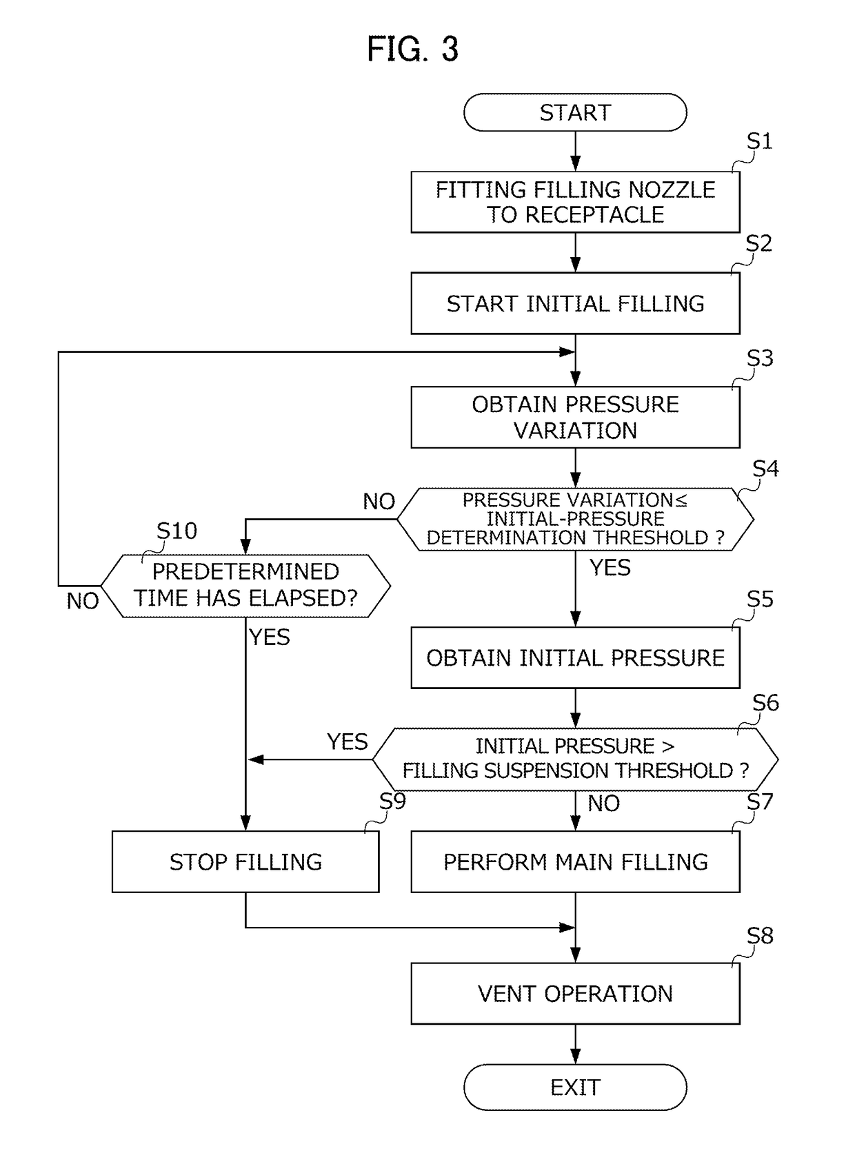
[0090]In the hydrogen gas filling method according to the first embodiment, an initial-pressure determination threshold is set for the pressure variation, and the initial pressure is obtained at a time when the value of the pressure variation obtained during initial filling becomes this initial-pressure determination threshold or less as described with reference to FIG. 3. The hydrogen gas filling method according to this embodiment differs from that according to the first embodiment b...

third embodiment

[0094]The hydrogen gas filling method according to the present invention is described above, but the present invention shall not be limited to this. Details in the configuration may appropriately be altered without departing the scope of the present invention.


PUM


Abstract

Provided is a gas filling method capable of accurately determining the initial pressure in a tank while minimizing increase in temperature and pressure regardless of the capacity of the tank. The gas filling method for connecting a supply source to a tank via a piping, and filling the tank with the gas, the method includes: an initial-filling initiation step of opening a flow control valve provided in the piping to start initial filling; a pressure-variation acquisition step of obtaining a pressure variation per unit time at a predetermined detection point downstream of the flow control valve in the piping; an initial-pressure detection step of obtaining a pressure at the detection point at a time specified using the pressure variation, and considering that pressure as the initial pressure in the tank; and a main-filling initiation step of starting main filling using the initial pressure.

Description

[0001]This application is based on and claims the benefit of priority from Japanese Patent Application No. 2015-178742, filed on 10 Sep. 2015, the content of which is incorporated herein by reference.BACKGROUND OF THE INVENTION[0002]Field of the Invention[0003]The present invention relates to a gas filling method. More specifically, the present invention relates to a gas filling method including connecting a supply source of a compressed gas to a tank mounted on a mobile object, and filling the tank with the gas.[0004]Related Art[0005]A fuel cell vehicle runs on a motor powered by a fuel cell where air containing oxygen and hydrogen gas as a fuel gas supplied thereto generate electricity. Fuel cell vehicles, in which those fuel cells are used as energy sources for generating power, recently have been becoming closer to practical use. Hydrogen gas is required to generate electricity in a fuel cell. A recent mainstream fuel cell vehicle uses tank-filled hydrogen gas for running, in wh...

Claims


Application Information

Patent Timeline
Patent Type & Authority Patents(United States)
IPC IPC(8): B65B1/04F17C1/00F17C5/06F17C13/08F17C5/00F17C13/04
CPCF17C5/06F17C5/007F17C13/084F17C13/04F17C1/005F17C2270/0763F17C2205/0326F17C2223/035F17C2223/036F17C2225/0123F17C2225/035F17C2225/036F17C2250/043F17C2201/056F17C2205/0332F17C2205/0335F17C2221/012F17C2223/0123F17C2227/0337F17C2227/0388F17C2250/032F17C2250/034F17C2250/0626F17C2250/0434F17C2250/0439F17C2250/0443F17C2250/0636F17C2260/025F17C2270/0139F17C2265/065Y02E60/32
Inventor HANDA, KIYOSHI
Owner HONDA MOTOR CO LTD
Why Eureka
Try Eureka