Compressed air cooling apparatus of fuel cell system

a technology of compressed air and fuel cell, which is applied in the field of compressed air cooling apparatus, can solve the problems of the efficiency of the fuel cell stack and the humidification efficiency, and achieve the effect of improving the cooling performance of compressed air

Active Publication Date: 2018-01-02
HYUNDAI MOTOR CO LTD
View PDF19 Cites 0 Cited by
  • Summary
  • Abstract
  • Description
  • Claims
  • Application Information

AI Technical Summary

Benefits of technology

[0012]In addition, the present invention provides a compressed air cooling apparatus of a fuel cell system that actively controls a temperature of compressed air under higher output power driving condition of a fuel cell stack, and improves air cooling performance and efficiency to provide a rapid increase in temperature of the compressed air.
[0031]According to the exemplary embodiments of the present invention, because the compressed air at a high temperature (e.g., above about 60° C. to 80° C.), which is supplied from the air compressor to the fuel cell stack, may be cooled by a simplified structure of the heat pipe which connects the heat absorber and the heat radiator, an excessive increase in temperature of the compressed air may be suppressed. Therefore, in the exemplary embodiments of the present invention, damage to the fuel cell stack due to heat of the compressed air may be prevented, and a temperature condition of the compressed air, which is appropriate for normally driving the fuel cell stack, may be satisfied.
[0032]In addition, in the exemplary embodiments of the present invention, because the compressed air of a high temperature may be prevented from being supplied to the humidifier, deterioration in humidifying efficiency of the humidifier and driving performance of the fuel cell stack may be prevented.
[0033]Moreover, in the exemplary embodiments of the present invention, because the compressed air at a high temperature may be cooled via a simplified structure of the heat pipe which connects the heat absorber and the heat radiator, the fuel cell system may be efficiently implemented in a reduced package.
[0034]Further, in the exemplary embodiments of the present invention, a temperature of the compressed air at the high temperature part may be controlled by adjusting an amount of the refrigerant, which is supplied from the heat radiator to the heat absorber, through the refrigerant supplier in accordance with a temperature of the compressed air, which is detected by the temperature sensor. Therefore, in the exemplary embodiments of the present invention, a temperature of the compressed air may be actively controlled under a high output power driving condition of the fuel cell stack, and air cooling performance may be improved by fast responsiveness to a rapid increase in temperature of the compressed air.
[0036]In addition, in the exemplary embodiments of the present invention, because the liquid refrigerant is supplied into the heat pipe through the pressure applicator by using pressure of the compressed air thereby pressing the liquid refrigerant inside the heat pipe during a process of cooling the compressed air, the movement of the liquid refrigerant inside the heat pipe may be accelerated. Therefore, in the exemplary embodiments of the present invention, the circulation of the refrigerant of the heat pipe is activated by using pressure of compressed air which flows through the air supply line, and thereby the cooling performance of the compressed air may be improved without using additional electrical control means.

Problems solved by technology

Since the aforementioned temperature is greater than 60 to 80° C., which is a normal driving temperature of the fuel cell stack, this creates problems in relation to humidification efficiency of the humidifier and driving efficiency of the fuel cell stack.

Method used


Image

  • Compressed air cooling apparatus of fuel cell system
  • Compressed air cooling apparatus of fuel cell system
  • Compressed air cooling apparatus of fuel cell system

Examples


Embodiment Construction

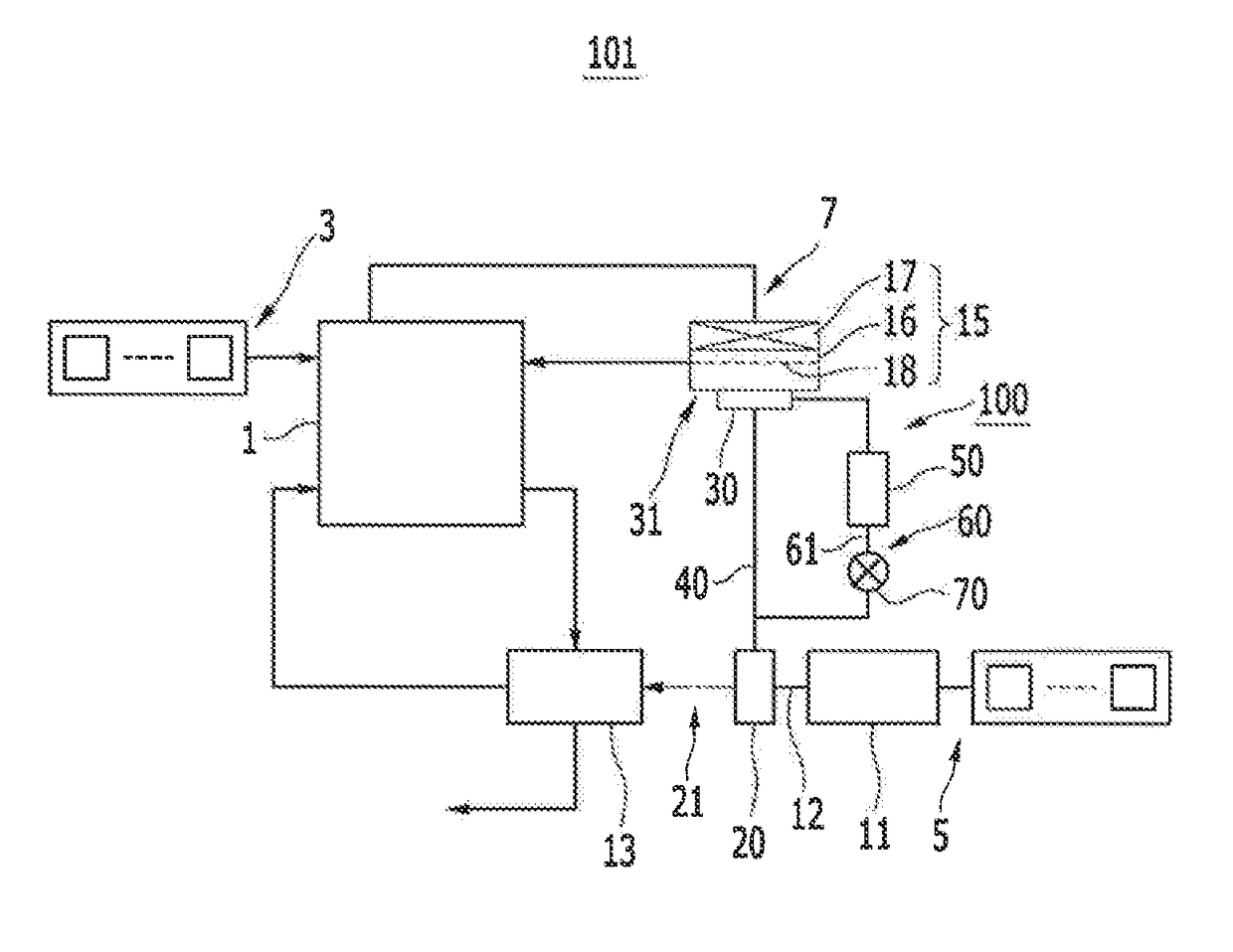
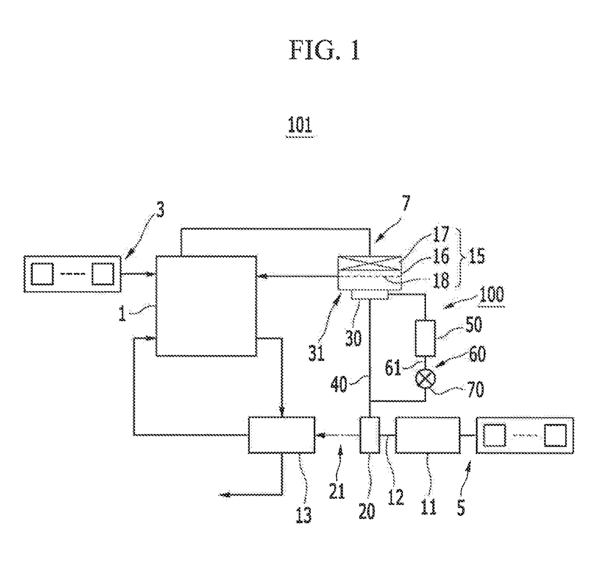
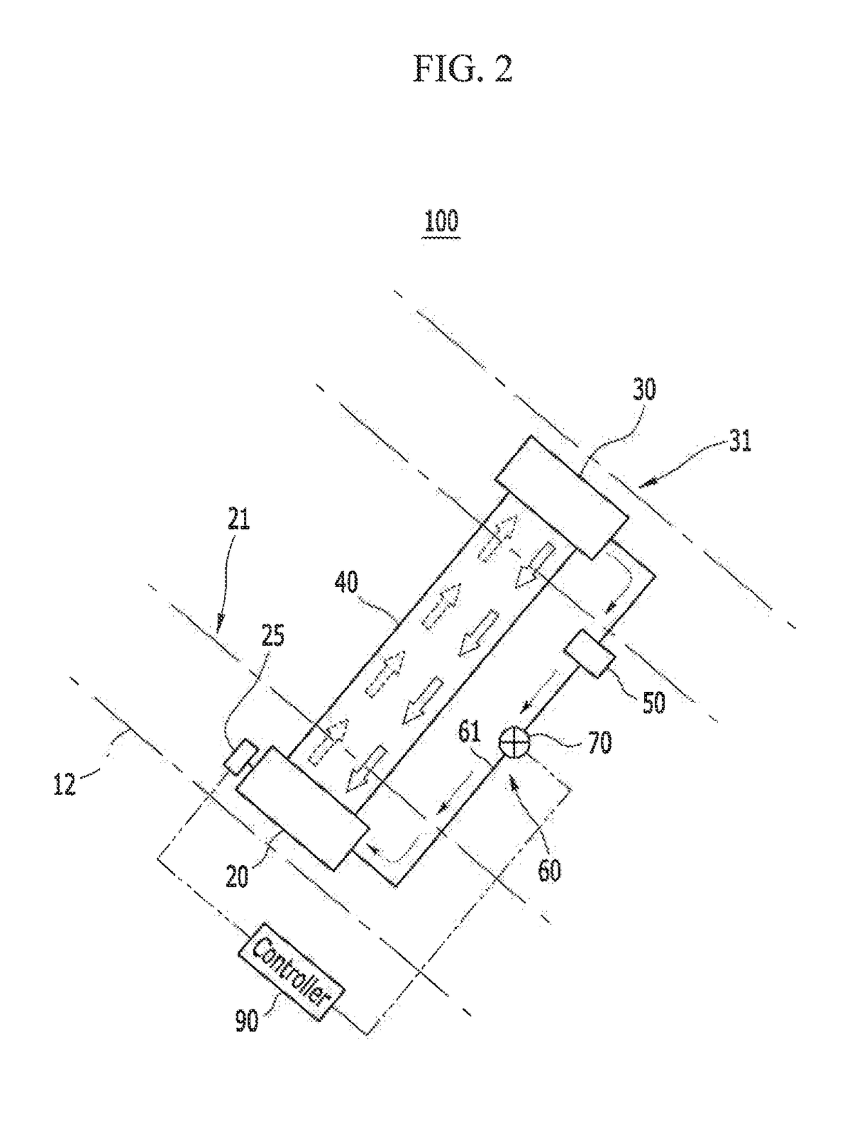
[0051]The present invention will be described more fully hereinafter with reference to the accompanying drawings, in which exemplary embodiments of the invention are shown. As those skilled in the art would realize, the described embodiments may be modified in various different ways, all without departing from the spirit or scope of the present invention.

[0052]It is understood that the term “vehicle” or “vehicular” or other similar term as used herein is inclusive of motor vehicles in general such as passenger automobiles including sports utility vehicles (SUV), buses, trucks, various commercial vehicles, watercraft including a variety of boats and ships, aircraft, and the like, and includes hybrid vehicles, electric vehicles, plug-in hybrid electric vehicles, hydrogen-powered vehicles, fuel cell vehicles and other alternative fuel vehicles (e.g. fuels derived from resources other than petroleum). As referred to herein, a hybrid vehicle is a vehicle that has two or more sources of p...


PUM

PropertyMeasurementUnit
temperatureaaaaaaaaaa

Abstract

A compressed air cooling apparatus of a fuel cell system is provided that includes i) a heat absorber installed at a first part of an air supplying system which supplies compressed air of a first compressed by an air compressor to a fuel cell stack, ii) a heat radiator installed at a second part of a stack cooling system which cools a coolant circulating to the fuel cell stack, iii) a heat pipe which connects the heat absorber and the heat radiator and is filled with the refrigerant therein, wherein the heat absorber is disposed at a lower position than the heat radiator for the refrigerant to flow from the heat radiator to the heat absorber.

Description

CROSS-REFERENCE TO RELATED APPLICATION[0001]This application claims priority to and the benefit of Korean Patent Application No. 10-2012-0132515 filed in the Korean Intellectual Property Office on Nov. 21, 2012, the entire contents of which are incorporated herein by reference.BACKGROUND[0002](a) Field of the Invention[0003]An exemplary embodiment of the present invention relates to a fuel cell system, and more particularly, to a compressed air cooling apparatus capable of cooling compressed air which is supplied to a fuel cell stack through an air compressor.[0004](b) Description of the Related Art[0005]In general, a fuel cell system supplies hydrogen, which is used as fuel, and air, which is an oxidant, to a fuel cell stack, and electricity is produced by an electrochemical reaction of the hydrogen and the oxygen within the fuel cell stack. When a fuel cell system is mounted in a vehicle, and the vehicle is driven by operating an electric motor with electricity produced by the fue...

Claims


Application Information

Patent Timeline
Patent Type & Authority Patents(United States)
IPC IPC(8): F28D15/06H01M8/04007H01M8/04014H01M8/04089H01M8/04119
CPCH01M8/04074F28D15/06H01M8/04014H01M8/04141H01M8/04089Y02E60/50F25D17/00H01M8/04
Inventor NOH, YONG GYULEE, MINKYUJUNG, SEKWON
Owner HYUNDAI MOTOR CO LTD
Why Eureka
Try Eureka