
Fuel cell system and method for controlling the same

a fuel cell and system technology, applied in battery/fuel cell control arrangement, electrochemical generators, transportation and packaging, etc., can solve the problems of reducing the efficiency of fuel cell heating, increasing the temperature of fuel cell slack, and increasing the angular speed of rotating magnetic field. , to achieve the effect of maximizing the iron loss of the induction motor, increasing the temperature of the fuel cell slack, and increasing the angular speed of the rotating magnetic field

Active Publication Date: 2015-12-17
HYUNDAI MOTOR CO LTD
View PDF3 Cites 0 Cited by
  • Summary
  • Abstract
  • Description
  • Claims
  • Application Information

AI Technical Summary

Benefits of technology

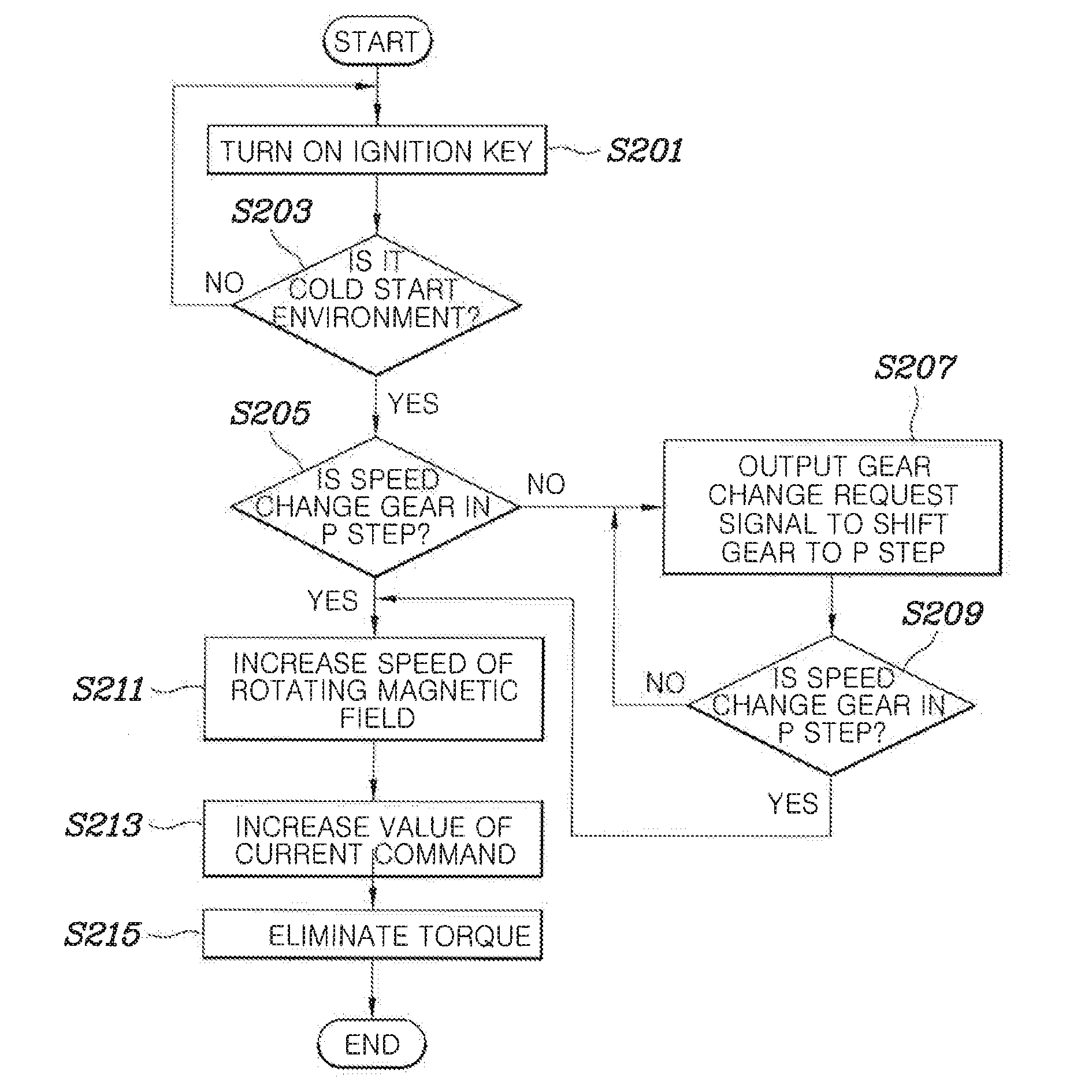
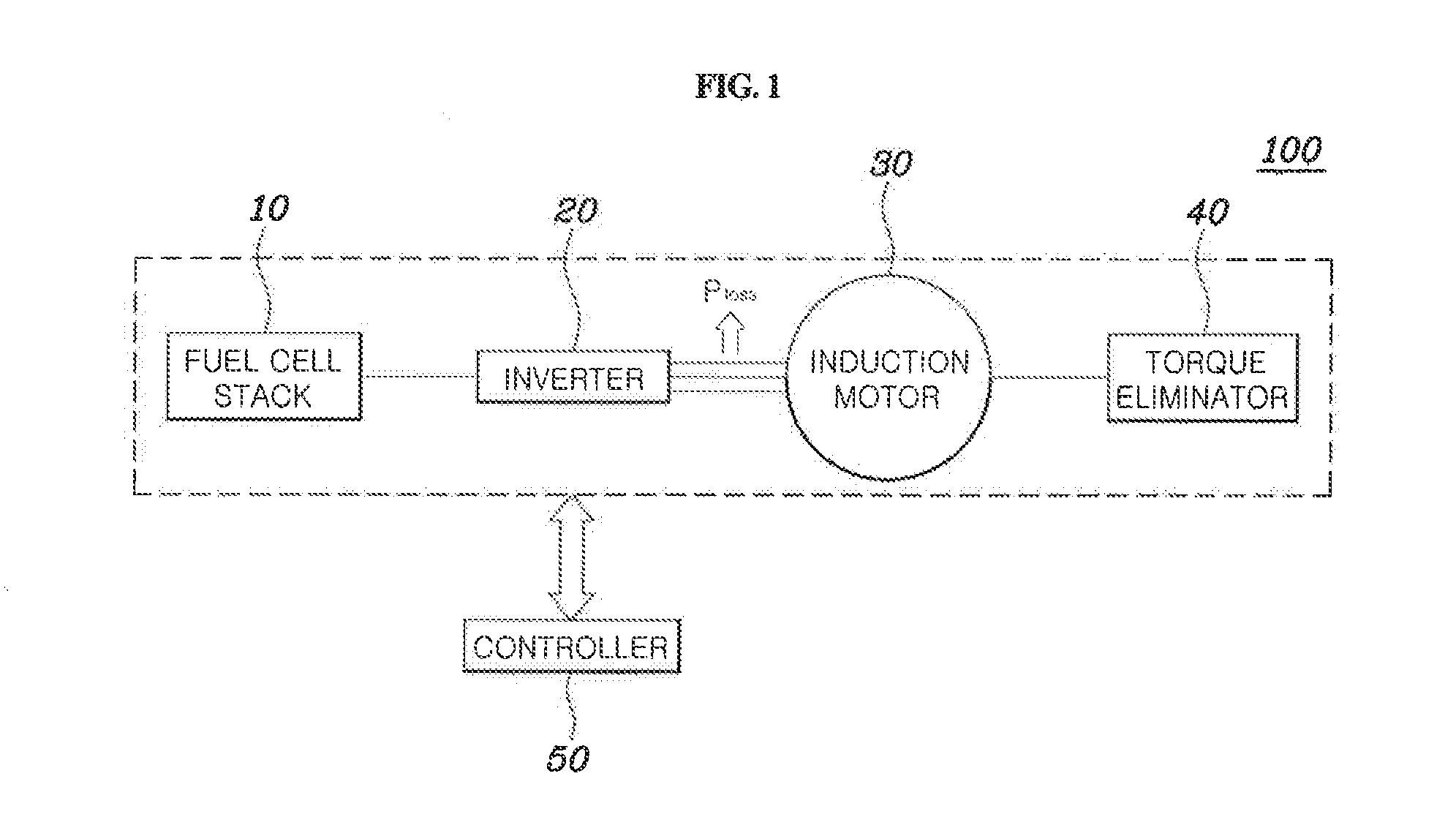
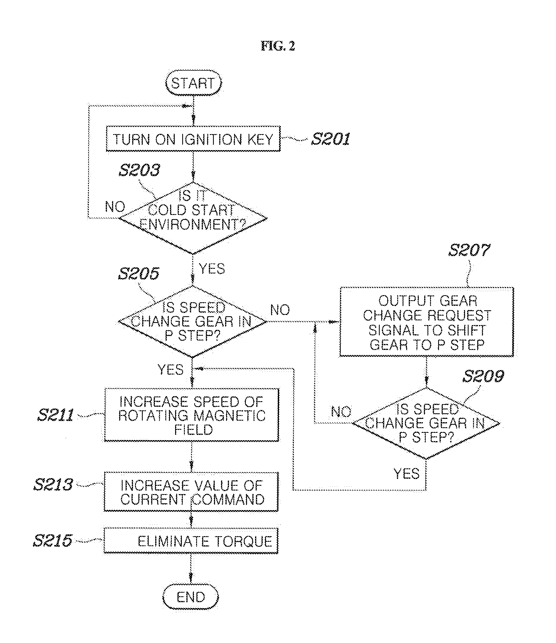
This patent describes a fuel cell system and method for controlling it that can quickly increase the temperature of a fuel cell stack using an induction motor. The method includes rapidly increasing the angular speed of the motor to maximize iron loss, while eliminating torque generated by the increased speed using a torque eliminator. The system can also determine if a gear change is needed and increase the angular speed of the motor accordingly. Additionally, the method can also increase the value of the motor's current to further increase the temperature of the fuel cell stack. The main technical effect is to enhance the efficiency and stability of the fuel cell system by promoting electrochemical reactions and reducing motor waste heat.

Problems solved by technology

When the exterior temperature is substantially low (e.g., below a predetermined temperature) the remaining water typically freezes and may eventually become ice and disable the start of an engine.
Some examples of disadvantages are an additional heater is necessary to heat the fuel cell stack and the fuel cell stack requires a structural change.
In other words, the necessary changes complicate the arrangement and design of constituent parts and increase the manufacturing cost.
Furthermore, heating the fuel cell stack to a desired level using the heater requires a substantial increase in time.

Method used


Image

  • Fuel cell system and method for controlling the same
  • Fuel cell system and method for controlling the same
  • Fuel cell system and method for controlling the same

Examples


Embodiment Construction

[0022]The terminology used herein is for the purpose of describing particular embodiments only and is not intended to be limiting of the invention. As used herein, the singular forms “a”, “an” and “the” are intended to include the plural forms as well unless the context clearly indicates otherwise. It will be further understood that the terms “comprises” and / or “comprising,” when used in this specification, specify the presence of stated features, integers, steps, operations, elements, and / or components, but do not preclude the presence or addition of one or more other features, integers, steps, operations, elements, components, and / or groups thereof. As used herein, the term “and / or” includes any and all combinations of one or more of the associated listed items.

[0023]Although exemplary embodiment is described as using a plurality of units to perform the exemplary process, it is understood that the exemplary processes may also be performed by one or plurality of modules. Additional...


PUM

PropertyMeasurementUnit
temperatureaaaaaaaaaa
angular speedaaaaaaaaaa
magnetic fieldaaaaaaaaaa

Abstract

A fuel cell system and a method tor controlling the same are provided. The method includes rapidly increasing an angular speed of a rotating magnetic field of an induction motor to maximize iron loss of the induction motor, thereby resulting in an increase in the temperature of a rise cell stack. The method further includes eliminating torque of a driving motor generated by an increase in the angular speed of the rotating magnetic field, using a torque eliminator. The torque eliminator includes a P-stage reducer or a hydraulic break.

Description

CROSS-REFERENCE(S) TO RELATED APPLICATION[0001]The present application claims priority to Korean Patent Application Number 10-2014-0070967 filed on Jun. 11, 2014, which is incorporated herein in its entirety.BACKGROUND[0002]1. Field of the Invention[0003]The present invention relates to a fuel cell system and a method for controlling the same, and more particularly to a fuel cell system and a method for controlling the same which rapidly increases a temperature of a fuel cell stack under cold start conditions.[0004]2. Description of the Related Art[0005]A fuel cell vehicle includes a fuel cell stack in which a plurality of fuel cells used as a driving power source are stacked, a fuel feeding system configured to feed hydrogen, that operates as a fuel, to the fuel cell stack, an air feeding system configured to feed air, which is used as an oxidizing agent in an electrochemical reaction in the fuel cell stack, and a heat-and-water management system configured to adjust a temperature ...

Claims


Application Information

Patent Timeline
Patent Type & Authority Applications(United States)
IPC IPC(8): H01M8/04
CPCH01M8/04067H01M8/04268H01M8/0432H01M8/04701H01M2250/20H01M8/04302B60L2260/167B60L2260/22B60L58/31B60L58/34Y02T90/40Y02E60/50H01M8/04223H01M8/04298
Inventor KWON, SOON WOOLEE, JOON YONG
Owner HYUNDAI MOTOR CO LTD
Learn More