Vibration measurement and analysis

a vibration analysis and measurement method technology, applied in the direction of measurement devices, instruments, machine gearing/transmission testing, etc., can solve the problems of difficult fault detection, particularly vulnerable gear boxes, and previous methods of vibration analysis that have generally failed to accurately and reliably detect faults in complex machines

Active Publication Date: 2019-01-01
TENSOR SYST PTY LTD
View PDF2 Cites 139 Cited by
  • Summary
  • Abstract
  • Description
  • Claims
  • Application Information

AI Technical Summary

Benefits of technology

[0031]filtering the signal in the time domain using a two pole Butterworth filter or a drift filter to reduce the resulting transients;
[0072]filtering the signal in the time domain using for example a standard two pole Butterworth filter or a drift filter to minimize the resulting transients;
[0078]The settling time may be reduced and the initial transient response removed so that the filter initial response can be effectively removed from a finite length data set.

Problems solved by technology

Gear boxes are particularly vulnerable to faults due to the high stresses exerted onto the individual tooth and bearing parts.
In large and complex machines fault detection is difficult due to the size of the gears and a lack of physical access afforded to operators when the machine is in use.
However, previous methods of vibration analysis have generally failed to accurately and reliably detect faults in complex machines.
The drawbacks of these past approaches include:1. a reliance on a constant shaft speed, and2. a tendency to search for gear and bearing artefacts within the same spectral components.
In practice the rotational speed of a machine may not be constant, due to the presence of start-up and shutdown phases, load variation or motor wandering during operation, and as a result the spectrum bandwidth varies leading to an inaccurate fault detection capability.

Method used


Image

  • Vibration measurement and analysis
  • Vibration measurement and analysis
  • Vibration measurement and analysis

Examples


Embodiment Construction

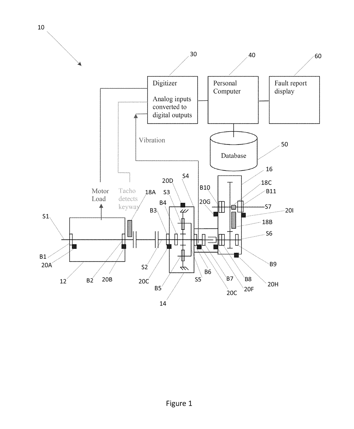
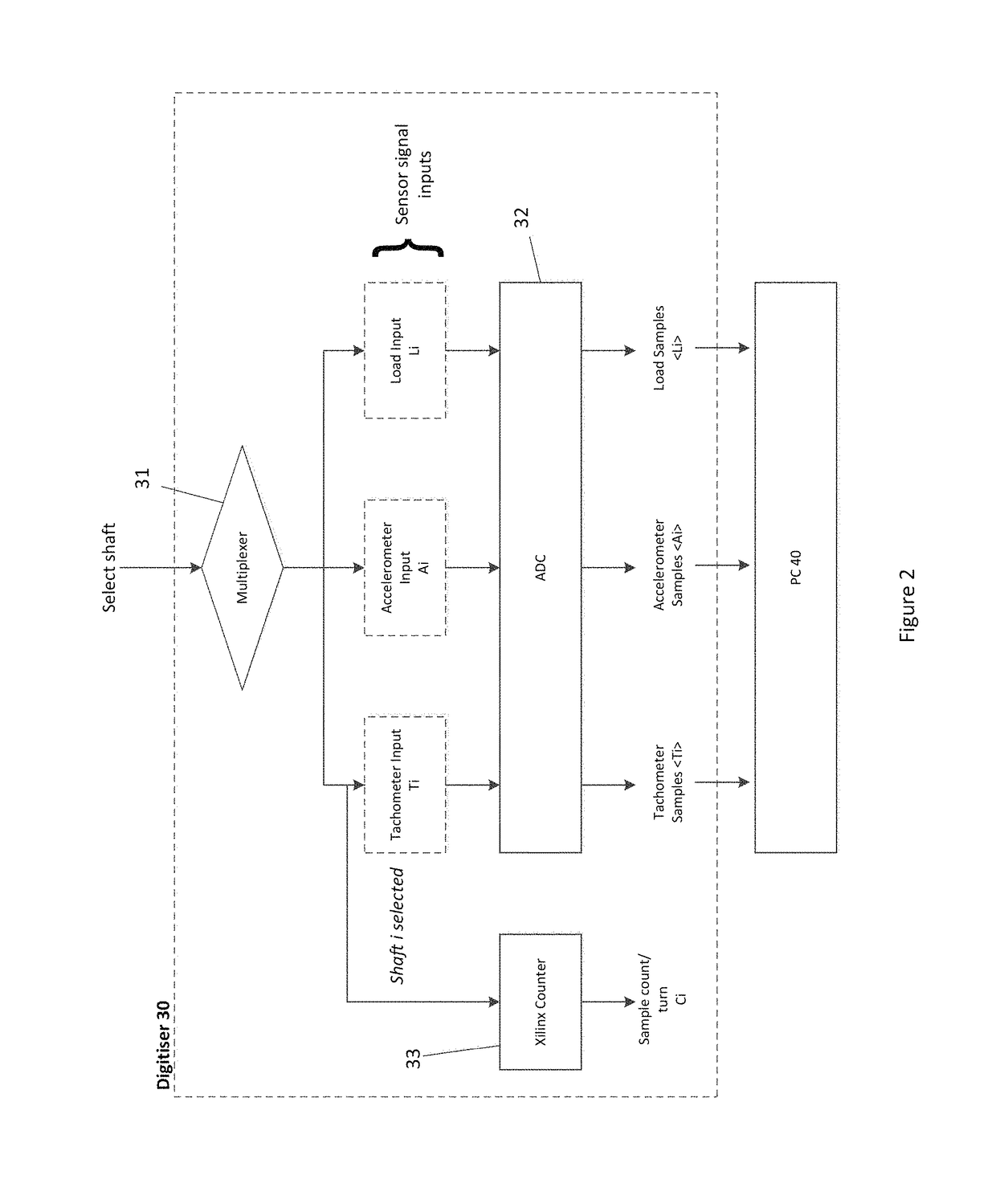
[0180]According to a preferred embodiment of the invention, there is described herein a vibration measurement and analysis method for advance fault detection of rotating components, such as gears and bearings. The method utilises signals from various sensors, such as load, speed and direction sensors, vibration and displacement sensors, fixed to one or more reference shafts, to record vibration for analysis. The method may include characterisation of gear meshing and bearing vibration through a separation of synchronous and non-synchronous components.

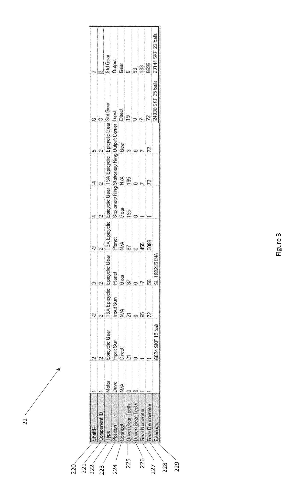
[0181]According to a preferred embodiment of the invention the method includes the steps of: establishing and tabulating in integer form parameters of rotating components of the mechanical system in a specification table, the parameters including type, gear configuration, bearing configuration and the relationships between the rotating components within the system; establishing a measurement specification and communicating same to a dig...


PUM


Abstract

A method of measuring and analyzing vibrations of a mechanical system, e.g., for performing gear and bearing fault detection within a system having a reference shaft and a plurality of rotating components. The method may include the steps of tabulating gear ratios of the plurality of rotating components relative to the reference shaft in integer form, establishing a measurement specification and communicating the measurement specification to a digitizer, recording vibration data from the mechanical system during operation, and resampling the recorded vibration data using the tabulated gear ratios to obtain vibration data corresponding to the rotating components and a vibration signature for a component of interest at predetermined angular increments.

Description

FIELD OF THE INVENTION[0001]The present invention relates to a vibration measurement and analysis method and system, for example the method and system are operable for performing gear and bearing fault detection within a machine having elements under periodic motion or rotation.BACKGROUND OF THE INVENTION[0002]Complex machinery is critically important to the functionality of many modern industrial systems. Rotating machines, such as turbines, generators, motors and engines are particularly important due to their ability to facilitate the process of converting energy to work. To achieve this rotating machinery typically comprises, or are at least configured with, gear systems. These machines operate via the rotation of interconnected shafts with attached gears in order to drive a load. In applications involving large loads, such as ore crushes and bar mills, gears, shafts and other components within the machines are placed under extreme stress. Ensuring the efficient and safe operati...

Claims


Application Information

Patent Timeline
Patent Type & Authority Patents(United States)
IPC IPC(8): G01M13/02G01M13/04
CPCG01M13/021G01M13/045G01M13/028
Inventor MOREY, JOHN ADRIANSTEWARD, JAMES EDWARD
Owner TENSOR SYST PTY LTD
Why Eureka
Try Eureka