
Implantable device

a medical device and implantable technology, applied in the field of permanent or temporary implantable medical devices, can solve the problems of the use of filter elements integrated into the electrode body, and the heat generation of the electrical conductor of the implantable medical device, so as to reduce the heat generation of the electrode line or the catheter in the mri scanner

Inactive Publication Date: 2019-01-08
BIOTRONIK SE & CO KG
View PDF9 Cites 0 Cited by
  • Summary
  • Abstract
  • Description
  • Claims
  • Application Information

AI Technical Summary

Benefits of technology

[0015]According to one or more embodiments, the implantable medical device, such as the electrode line, that transforms energy for at least one specific wavelength in the electrical line. For example, the energy that is coupled in, via electromagnetic or magnetic alternating fields, at the point at which electrical signals (for example stimulation or sensing signals) are decoupled, and specifically the amplitude of coupled-in electromagnetic waves is minimized. One or more embodiments may include a parallel incorporation or connection of the heat-reducing second electrical component in series for example, such that the effects on the function of the implantable medical device are reduced and damage to the second electrical component does not pose a risk for the functionality of the implantable medical device. At least one embodiment of the invention includes a high level of flexibility of the electrode line, in terms of the geometric design, which enables implementation of the electrode line using established design concepts.
[0017]Embodiments of the invention thus provide advantageous physiological properties, implemented with a smaller and more flexible electrode line. The risk of tissue irritation and perforation decreases and the longevity of the construction is increased.
[0039]In at least one embodiment, the combination of the at least one second electrical component and the dielectric medium may be in contact with an electrically conductive surface. Such a contact, in at least one embodiment, may act as a ground plate and may increase the effective permittivity of the device.

Problems solved by technology

Implantable medical devices, for example electrode lines for electrostimulation, have the disadvantage that their electrical conductor heats up in an electromagnetic alternating field, for example in an MRI scanner, because electromagnetic alternating fields induce electrical currents in the electrical conductor.
Generally, another disadvantage of typical implantable medical devices include the use of filter elements integrated into the electrode body.
The electrode line structure is thus weakened in terms of the electrode line physiological properties, wherein the electrode line is larger and more rigid, such that the risk of tissue irritation and perforation increases.
As such, generally, the longevity of the structure or construction is thus jeopardized or restricted.
Generally, functional conductors are electrical conductors necessary for the functions of the respective electrode line and, as such, are typically exposed to the risk that electrical currents will be induced in them as a result of external alternating magnetic fields.
Typically, this may lead to an undesired heating of the functional conductors or of the electrode poles connected thereto, or may lead to delivery of corresponding currents via the electrode poles to surrounding tissue and therefore heating of the surrounding tissue.

Method used


Image

  • Implantable device
  • Implantable device
  • Implantable device

Examples


Embodiment Construction

[0052]The following description is of the best mode presently contemplated for carrying out at least one embodiment of the invention. This description is not to be taken in a limiting sense, but is made merely for the purpose of describing the general principles of the invention. The scope of the invention should be determined with reference to the claims.

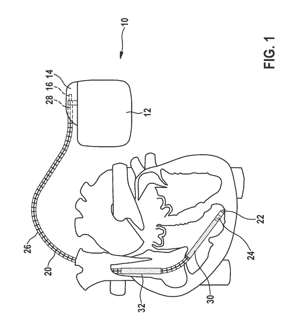
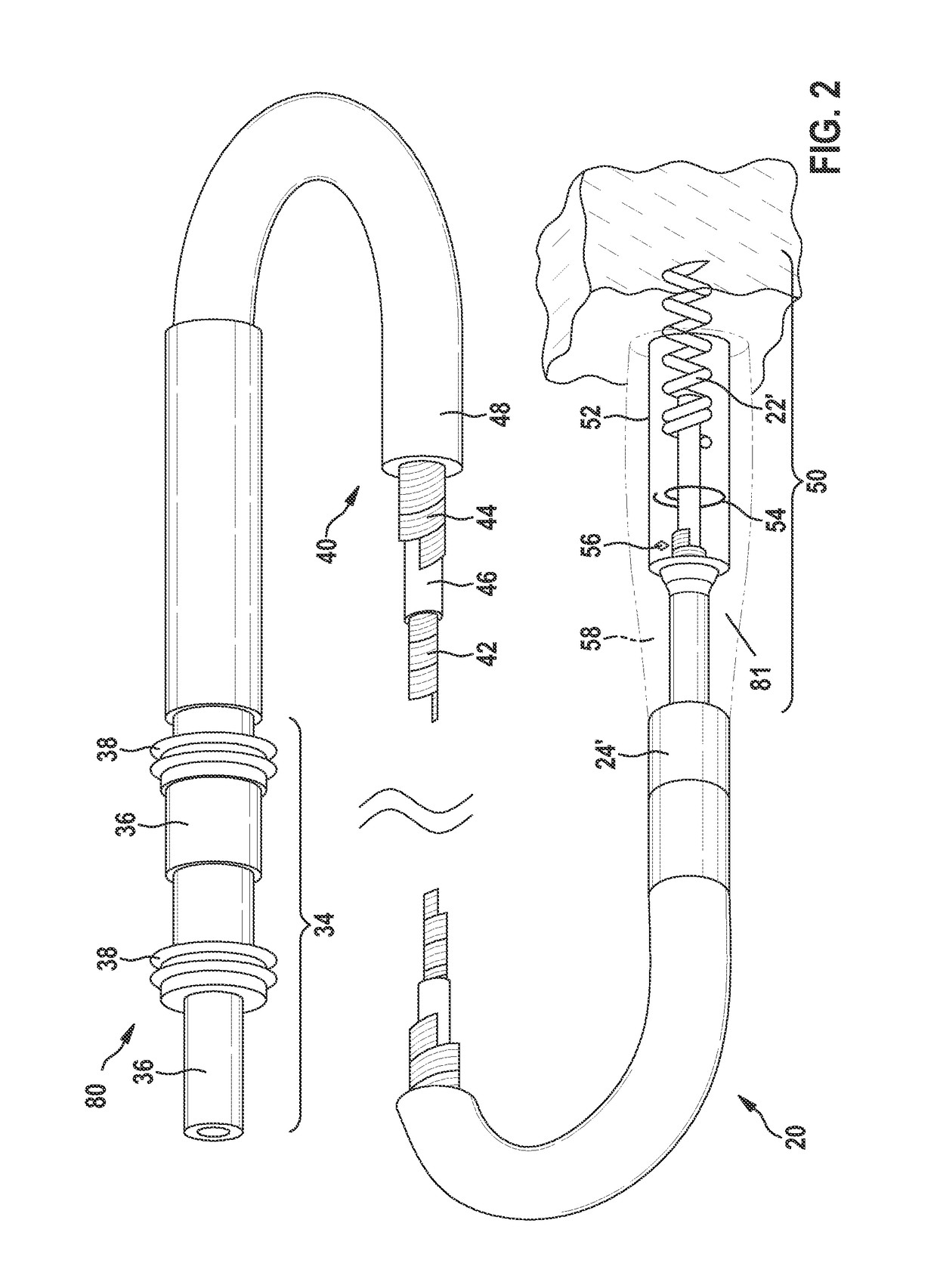
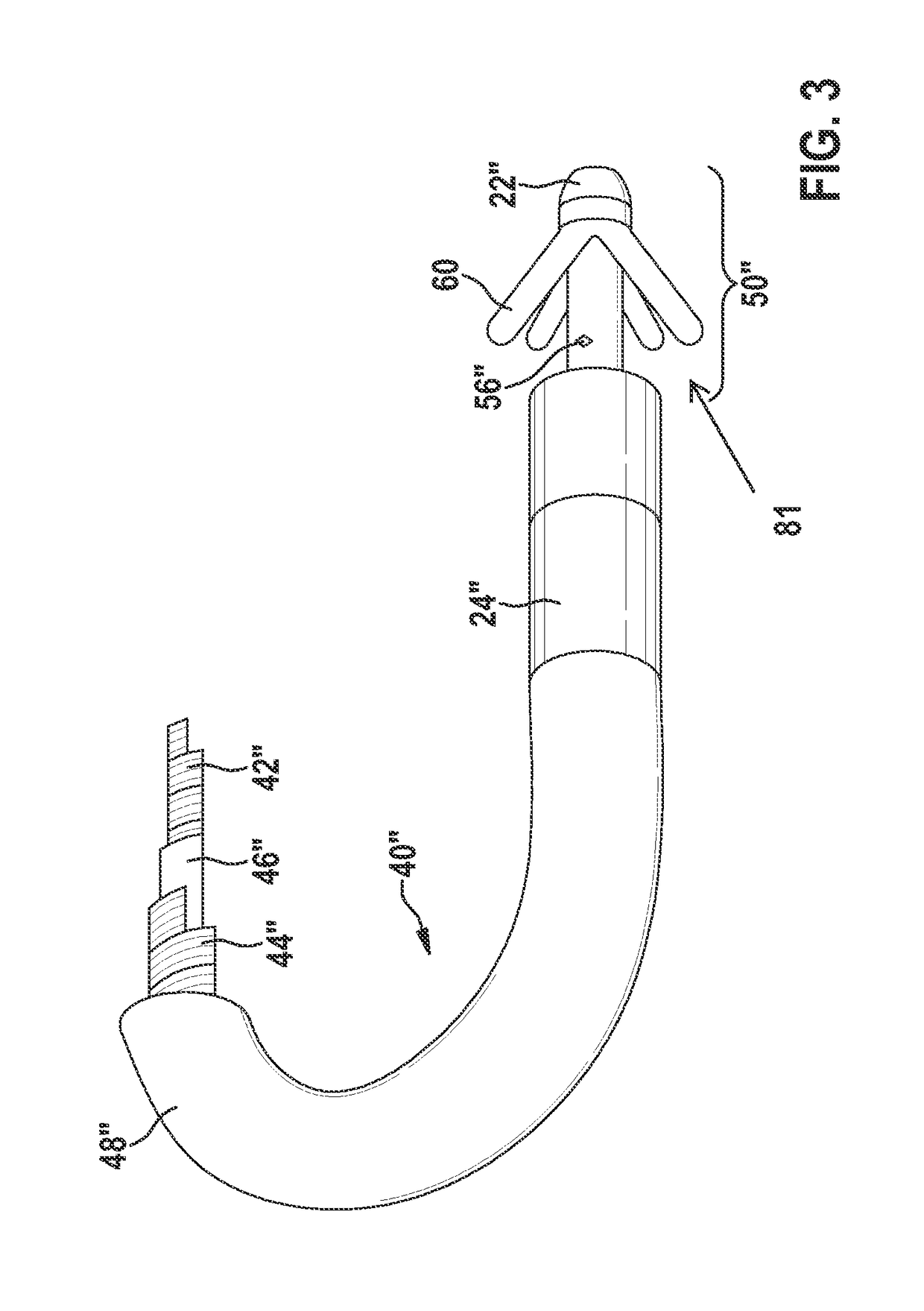
[0053]FIG. 1 shows an implantable heart stimulator 10 and an implantable electrode line 20 connected thereto, according to at least one embodiment of the invention.

[0054]In one or more embodiments, the implantable heart stimulator 10 may include a cardiac pacemaker or an implantable cardioverter-defibrillator (ICD). In at least one embodiment of the invention, the heart-stimulator 10 may include a ventricular cardiac pacemaker and defibrillator, a dual-chamber cardiac pacemaker that stimulate a right atrium and a right ventricle of the heart, or a biventricular cardiac pacemaker that stimulates the right ventricle and a left ventri...


PUM


Abstract

An implantable medical device including at least one elongate electrical line with a first electrical component as a functional conductor, and at least one second electrical component with an electrical length. The first electrical component includes a proximal end and a distal end, wherein the distal side is in electrical contact with tissue or blood. The first electrical component is in electrical contact with the at least one second electrical component, and wherein the electrical length of the at least one second component corresponds to at least a tenth of a wavelength (λ / 10) of electromagnetic waves in a radiofrequency range.

Description

[0001]This application claims the benefit of U.S. Provisional Patent Application 61 / 877,298 filed on 13 Sep. 2013, the specification of which is hereby incorporated herein by reference.BACKGROUND OF THE INVENTION[0002]Field of the Invention[0003]Embodiments of the invention generally relate to a permanently or temporarily implantable medical device including an elongate electrical conductor.[0004]Description of the Related Art[0005]Implantable medical devices, for example electrode lines for electrostimulation, have the disadvantage that their electrical conductor heats up in an electromagnetic alternating field, for example in an MRI scanner, because electromagnetic alternating fields induce electrical currents in the electrical conductor.[0006]Specifically, at least one stimulation electrode line is typically connected to implantable cardiac pacemakers or defibrillators. At a proximal end of the line, which is intended for connection to the cardiac pacemaker or defibrillator, ther...

Claims


Application Information

Patent Timeline
Patent Type & Authority Patents(United States)
IPC IPC(8): A61N1/08A61B5/00A61N1/05
CPCA61N1/08A61B5/6846A61N1/056A61N1/05A61N1/086
Inventor KOLBERG, GERNOTRUMP, JENSFRIEDRICH, MICHAELBUESSING, HEINRICHKNORR, STEFANBITZER, ANDREASTEAUBERT, KERSTINWEISS, INGOBARTELS, KLAUSMAXFIELD, MICHELLELENSKI, HARTMUTFRENZEL, TIMOTRIP, ERIK
Owner BIOTRONIK SE & CO KG
Learn More