Interface device for tensioning a nut and a bolt assembly

a technology of interface device and nut, which is applied in the direction of spanners, metal-working hand tools, wrenches, etc., can solve the problems of not always available space, the required diameter of the hydraulic cylinder in the jack, and the bolt tension is not uniform, so as to achieve torque free tensioning

Active Publication Date: 2019-01-08
HYTORC NORGE
View PDF10 Cites 4 Cited by
  • Summary
  • Abstract
  • Description
  • Claims
  • Application Information

AI Technical Summary

Benefits of technology

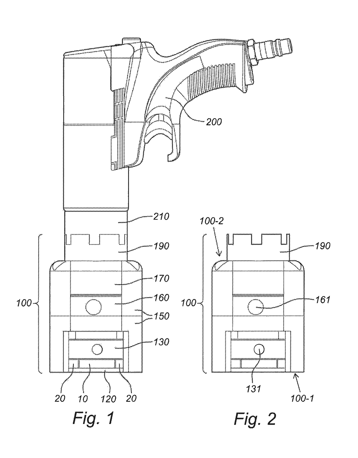
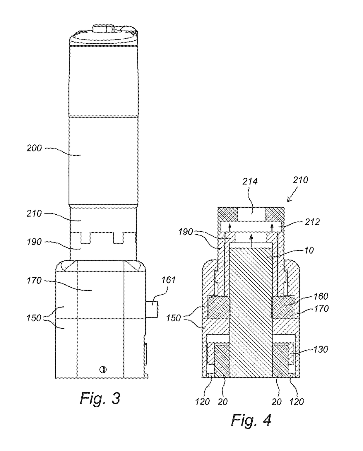
[0014]In a first aspect the invention relates to an interface device for tensioning or relaxing a bolt in a nut-and-bolt assembly. The bolt extends in an axial direction. The interface device comprises a frame having a first end portion and a second end portion, opposite to the first end portion. The first end portion of the frame being provided with a rotatably mounted nut ring for receiving and rotating a conventional nut provided on the bolt in operational use of the interface device. The second end portion of the frame comprising a mechanical tensioner nut being configured for reacting on the frame and for receiving a part of the bolt that extends beyond the conventional nut in operational use of the interface device. The mechanical tensioner nut is further configured for being driven by a low-pressure torque tension tool to tension or relax the bolt in operational use of the interface device.
[0015]The effects of the combination of the features of the invention are as follows. Instead of using a hydraulic cylinder to set the tension in the shank of the bolt, the interface device of the invention uses a relatively mechanical small device namely the mechanical tensioner nut, which in the prior art is used as a replacement for conventional nuts. Moreover, such mechanical device may be torqued using conventional low pressure (and thus compact) tension tools. In this way the invention provides for a very compact torqueing solution, contrary to the prior art solution with the hydraulic cylinder.
[0016]For a proper understanding of the scope of the invention a few expressions and terms are further defined in this paragraph. In the context of the invention with the term “low-pressure torque tension tool” is typically meant an air-pressure tension tool, which operates at pressures in the range from 2 bar to 20 bar, and preferably between 5 and 6 bar.
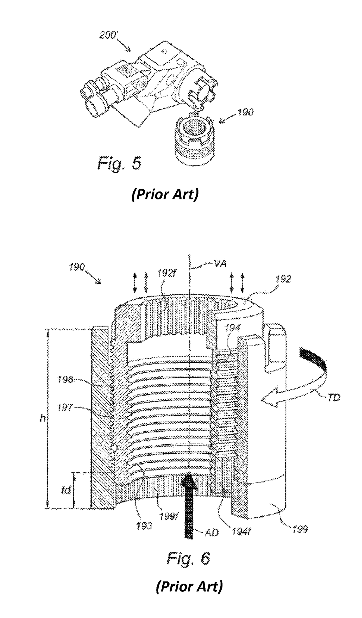
[0017]In the context of the invention the terms “bolt” and “stud” are supposed to mean the same. Such terms may be used interchangeably. In the context of the invention with the term “mechanical tensioner nut” is typically meant a special non-conventional nut which enables a torque free tensioning by converting a rotational movement into a translational movement. Various types and variations of the mechanical tensioner nuts have been reported in the prior art, for instance in U.S. Pat. Nos. 5,318,397, 5,341,560, 5,538,379, 5,946,789, 6,490,952Bw. All these documents are herewith incorporated by reference in their entirety. in general the mechanical tensioner nut relies upon converting a rotating movement around a thread on a bolt into a translation of said bolt, thereby tensioning or relaxing the bolt. A commercially available mechanical tensioner nut is the Hytorc Nut ™ .
[0018]An embodiment of the interface device according to the invention further comprises a pressure measure device in between the mechanical tensioner nut and the frame for measuring a reaction force of the mechanical tensioner nut on the frame as an indication of a tension in a shank of the bolt. Adding a pressure measure device between the mechanical tensioner nut and the frame results in a tool, with which the tension in the shank of the bolt can be bolt can be conveniently set to a predetermined value. In the context of the invention it must be understood that “the predetermined value of the tension” may also be denoted as the “pre-load on the bolt”.
[0019]In an embodiment of the interface device according to the invention the mechanical tensioner nut comprises a first part connectable with said bolt to pull said bolt in the axial direction for elongating said bolt and thereby for tensioning said bolt, or to relax said bolt by shortening said bolt. Said mechanical tensioner nut further comprises a second part connected with said first part, and a friction element configured for cooperating with at least one of said parts. Said second part is freely rotatable relative to said friction element while it freely abuts against said friction element. Said first part has a threaded outer surface and said second part has a threaded inner surface for cooperating with said threaded outer surface of said first part, so that, when the second part is rotated in a transverse direction around a virtual axis that extends in an axial direction of the mechanical tensioner nut, said first part moves only in the axial direction so as to tension or relax said bolt, wherein the direction into which said first part moves depends on the rotational direction of the second part. The embodiment here described provides an advantageous embodiment of the mechanical tensioner nut, wherein a torque free tensioning is enabled by converting a rotational movement (namely of the second part) into a translational movement (of the first part).

Problems solved by technology

All of the older methods have one common problem, namely friction.
Variations in this friction loss, from bolt to bolt causes non-uniform tension in bolts that have been tightened to the same torque or impact wrench setting.
A severe disadvantage of the known hydraulic tensioner is that the required diameter of the hydraulic cylinder in the jack is directly proportional to the required tension in the shank of the bolt at a given pressure of the hydraulic cylinder.
In certain applications, like the pipeline or pressure vessel flanged connections, such space may not always be available.

Method used


Image

  • Interface device for tensioning a nut and a bolt assembly
  • Interface device for tensioning a nut and a bolt assembly
  • Interface device for tensioning a nut and a bolt assembly

Examples


Embodiment Construction

[0028]It should be noted that the above-mentioned embodiments illustrate rather than limit the invention, and that those skilled in the art will be able to design many alternative embodiments without departing from the scope of the appended claims. In the claims, any reference signs placed between parentheses shall not be construed as limiting the claim. Use of the verb “comprise” and its conjugations does not exclude the presence of elements or steps other than those stated in a claim. The article “a” or “an” preceding an element does not exclude the presence of a plurality of such elements. The invention may be implemented by means of hardware comprising several distinct elements, and by means of a suitably programmed computer. In the device claim enumerating several means, several of these means may be embodied by one and the same item of hardware. The mere fact that certain measures are recited in mutually different dependent claims does not indicate that a combination of these ...


PUM


Abstract

An interface device for tensioning or relaxing a bolt in a nut-and-bolt assembly wherein the bolt extends in an axial direction. The interface device comprises a frame having a first end portion and a second end portion. The first end portion is provided with a rotatably-mounted nut ring for receiving and rotating a conventional nut on the bolt. The second end portion comprises a mechanical tensioner nut configured for reacting on the frame and for receiving a part of the bolt that extends beyond the conventional nut. The mechanical tensioner nut is configured for being driven by a low-pressure torque tension tool to tension or relax the bolt in operational use of the interface device. The device provides a very compact torqueing solution for use with low-pressure torqueing tools.

Description

CROSS-REFERENCE TO RELATED APPLICATION[0001]This United States National Phase of PCT Application No. PCT / NO 2015 / 050043 filed 26 Feb. 2015, claims priority to Norwegian Patent Application No. 20140440 filed 4 Apr. 2014, each of which are incorporated herein by reference.STATEMENT REGARDING FEDERALLY SPONSORED RESEARCH OR DEVELOPMENT[0002]Not Applicable.NAMES OF PARTIES TO A JOINT RESEARCH AGREEMENT[0003]Not Applicable.INCORPORATION-BY-REFERENCE OF MATERIAL SUBMITTED ON A COMPACT DISC OR AS A TEXT FILE VIA THE OFFICE ELECTRONIC FILING SYSTEM[0004]Not Applicable.BACKGROUND OF THE INVENTION[0005]The invention relates to an interface device for tensioning or relaxing a bolt in a nut-and-bolt assembly.[0006]Hydraulic bolt tensioning exits already for many years. In the prior art a hydraulic bolt tensioning tool has been reported which provides a quick and easy method for tightening large diameter bolts to high and accurate pre-loads. Unlike earlier methods it does not use torque and does...

Claims


Application Information

Patent Timeline
Patent Type & Authority Patents(United States)
IPC IPC(8): B25B29/02B25B13/06
CPCB25B13/06B25B29/02
Inventor JAEGER, ANDREAS HOLSTHELMIKSTOL, RUBEN
Owner HYTORC NORGE
Why Eureka
Try Eureka