Maximum energy utilization point tracking technologies

a technology of maximum energy utilization and tracking technology, applied in greenhouse gas reduction, process and machine control, instruments, etc., can solve the problems of inextricable energy utilization efficiency, blind mppt practice does not match the characteristics of the energy extraction device, blind mppt practice does not match the device to prepare and/or deliver the extracted energy,

Active Publication Date: 2019-01-08
LT (USA) CORP
View PDF6 Cites 0 Cited by
  • Summary
  • Abstract
  • Description
  • Claims
  • Application Information

AI Technical Summary

Benefits of technology

[0011]In doing so, the principles described herein results in a practical optimization of maximum energy utilization solution for energy systems. Such is especially true for green energy systems, which convert electricity from renewable energy sources (such as the solar power, wind, tide, or wave motion) that have the characteristics of time varying intensity; thereby effectuating the maximum energy utilization point tracking (MEPT).

Problems solved by technology

First, the blind MPPT practice does not match the characteristics of the energy extraction device to effectively and efficiently exact the produced energy.
Second, the blind MPPT practice does not match the device to prepare and / or deliver the extracted energy for efficiently energy utilization.
Third, the energy utilization efficiency is not only inextricably dependent on power production but is also dependent on power demand.
Fourth, typical power consumption in any energy system is not equal to power production, even complying with the energy conservation law.
The practice of blind MPPT conformation can lead commercial “green energy system” designers fail to experimentally determine the devices' effectiveness and efficiencies—such as the effectiveness and efficiency of energy extraction from the generator, and such as the effectiveness and efficiency of energy that is prepared and then delivered to the load.
However, the inventors' experimental measurements of many commercial systems reveal that the efficiency of energy extraction from the generator, and that of preparing and then delivering of the energy to the load can be very poor when regulating the system operation to blindly conform to the MPPP voltage.

Method used


Image

  • Maximum energy utilization point tracking technologies
  • Maximum energy utilization point tracking technologies
  • Maximum energy utilization point tracking technologies

Examples


Embodiment Construction

[0031]Section One: Review on Energy System

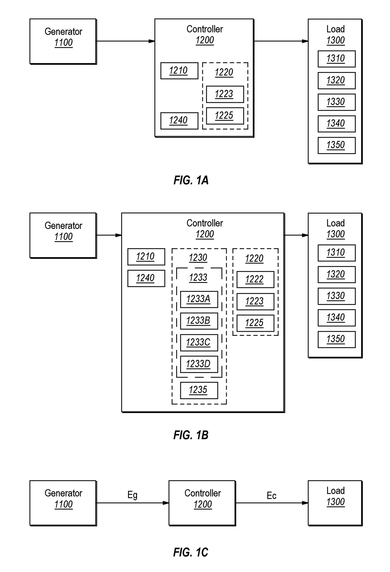
[0032]An energy system 1000 consists of generator(s) 1100, regulator(s) 1200, load(s) 1300; and all their module(s) thereof, which are described hereinafter and are depicted in FIGS. 1A, 1B and 1C. FIG. 1A depicts a conventional energy system block diagram; while FIG. 1B depicts a block diagram structure of an energy system in accordance with the principles described herein. The efficiency of any given subsystem is defined herein as the output of the given subsystem divided by the output of the previous subsystem. As a typical example, the regulator (or controller) efficiency is defined as the energy delivered to the load (Ec) divided by the energy produced by the generator (Eg) as depicted in FIG. 1C. The names of the modules depicted in FIG. 1 are listed as follows:[0033]1000: Energy system,[0034]1100: Generator,[0035]1200: Controller or regulator,[0036]1210: Conventional energy extraction device,[0037]1220: Module or device,[0038]1222: En...


PUM


Abstract

When one operates an energy system at its maximum energy utilization point (MEUP) consistently, one can receive the most amount of energy benefit from the system. The practical MEUP tracking technologies operate a generator at a voltage for maximum power extraction and to produce near-maximum power; incorporate the invented surplus energy extraction devices to near-perfectly extract all power generated; temporarily store the surplus energy into designed energy reservoirs; add the invented supply devices to combined the energy from the extractor and from the reservoirs; prepare and deliver the right amount of power to exactly satisfy the instantaneous demand. Thus effectuates finding and tracking the MEUP of the energy system.

Description

CROSS-REFERENCE TO RELATED APPLICATIONS[0001]This patent application is a continuation-in-part of U.S. patent application Ser. No. 14 / 880,101, filed Oct. 9, 2015, which patent application is incorporated herein by reference in its entirety.BACKGROUND[0002]Many “green energy” electric generators utilize natural renewable energy sources that are characterized as having time varying intensity. Examples of such renewable energy sources include solar power, wind, tide, and wave motion. Most of such power generators incorporate a device named the “maximum power point tracker (MPPT)” to track the instantaneous maximum power production point (MPPP) voltage. The MPPT device typically is firmware and keeps track of the time varying voltage resulting in the maximum power production from a primary energy source having time varying intensity.[0003]Typically, a commercial green energy system integrator applies the MPPP voltage to regulate the entire system operation including energy generation, t...

Claims


Application Information

Patent Timeline
Patent Type & Authority Patents(United States)
IPC IPC(8): H02J7/34H02J3/38G05F1/67H02S40/38
CPCH02J3/385G05F1/67H02S40/38Y02E10/58H02J7/34H02J2300/26H02J3/381Y02E10/56Y02E70/30
Inventor SHUY, GEOFFREY WEN-TAILAI, HSIN-CHENLI, CHANG-HORANG
Owner LT (USA) CORP
Why Eureka
Try Eureka