
Heat pump with accumulator at boost compressor output

a heat pump and compressor technology, applied in the direction of positive displacement liquid engine, heating type, lighting and heating apparatus, etc., can solve the problems of increasing the difficulty of drawing heat from the outdoor environment, reducing the energy cost of consumers, and increasing the difficulty of conventional heat pump systems in colder climates. achieve the effect of increasing the heating capacity and easily diverting hea

Inactive Publication Date: 2008-02-21
ELECTRO IND
View PDF69 Cites 45 Cited by
  • Summary
  • Abstract
  • Description
  • Claims
  • Application Information

AI Technical Summary

Benefits of technology

[0019] The preferred embodiment of the present invention provides increased heating capacity through the use of a primary compressor, a first boost compressor and a second boost compressor. The system effectively utilizes this heating capacity with four heat exchangers that provide 1) indoor air heating or cooling, 2) hydronic floor heating and 3) tap water heating. In addition to providing additional heating capabilities, the heat energy generated by the system may be easily diverted between the indoor air heating system, the hydronic floor heating system and the water heater to provide maximum comfort and energy utilization, store energy for later use and address fluctuations in the energy output of the system.
[0020] The system utilizes a novel control system that: 1) prevents unsafe operating parameters; 2) ensures comfortable indoor heating and cooling; 3) utilizes any excess energy present in the system, or stores that energy for later use, by diverting the energy to the hydronic floor heating system and / or the water heater and 4) provides for long run times of the system at optimal conditions to prevent unnecessary and intermittent start up of the compressors.

Problems solved by technology

Heat pump systems are also highly efficient, resulting in decreased energy costs to the consumer.
The use of conventional heat pump systems in colder climates, however, presents significant challenges.
At very low temperatures it becomes increasingly difficult to draw heat from the outdoor environment.
In addition, at low temperatures, the outdoor heat exchange coil is very susceptible to frost build up, which limits air flow across the coil.
As a result, the performance and efficiency of heat pump systems decreases drastically at very low ambient temperatures when heating capacity is most needed.
Single compressor systems have been utilized that can provide heating at low to moderate ambient temperatures, but such systems typically demonstrate decreased efficiency and performance at higher ambient temperatures relative to systems with less heating capacity.
Additionally, such systems must cycle on and off frequently at higher ambient temperatures, resulting in a reduced lifespan for the compressor and decreased system efficiency.
Variable speed compressors have been used to address this problem, but these types of compressors are expensive and lead to increased installation costs for the system.
These control methodologies, however, may lead to frequent calls for changes in compressor output, which will cause one or both of the compressors to cycle on and off.
Prior art systems, however, have not effectively integrated control of the back up heating system with the control of the heat pump system.
As a result, the back up heating system, which performs at lower efficiency, is over utilized as compared to the heat pump system, leading to increased energy costs.

Method used


Image

  • Heat pump with accumulator at boost compressor output
  • Heat pump with accumulator at boost compressor output
  • Heat pump with accumulator at boost compressor output

Examples


Embodiment Construction

System Design

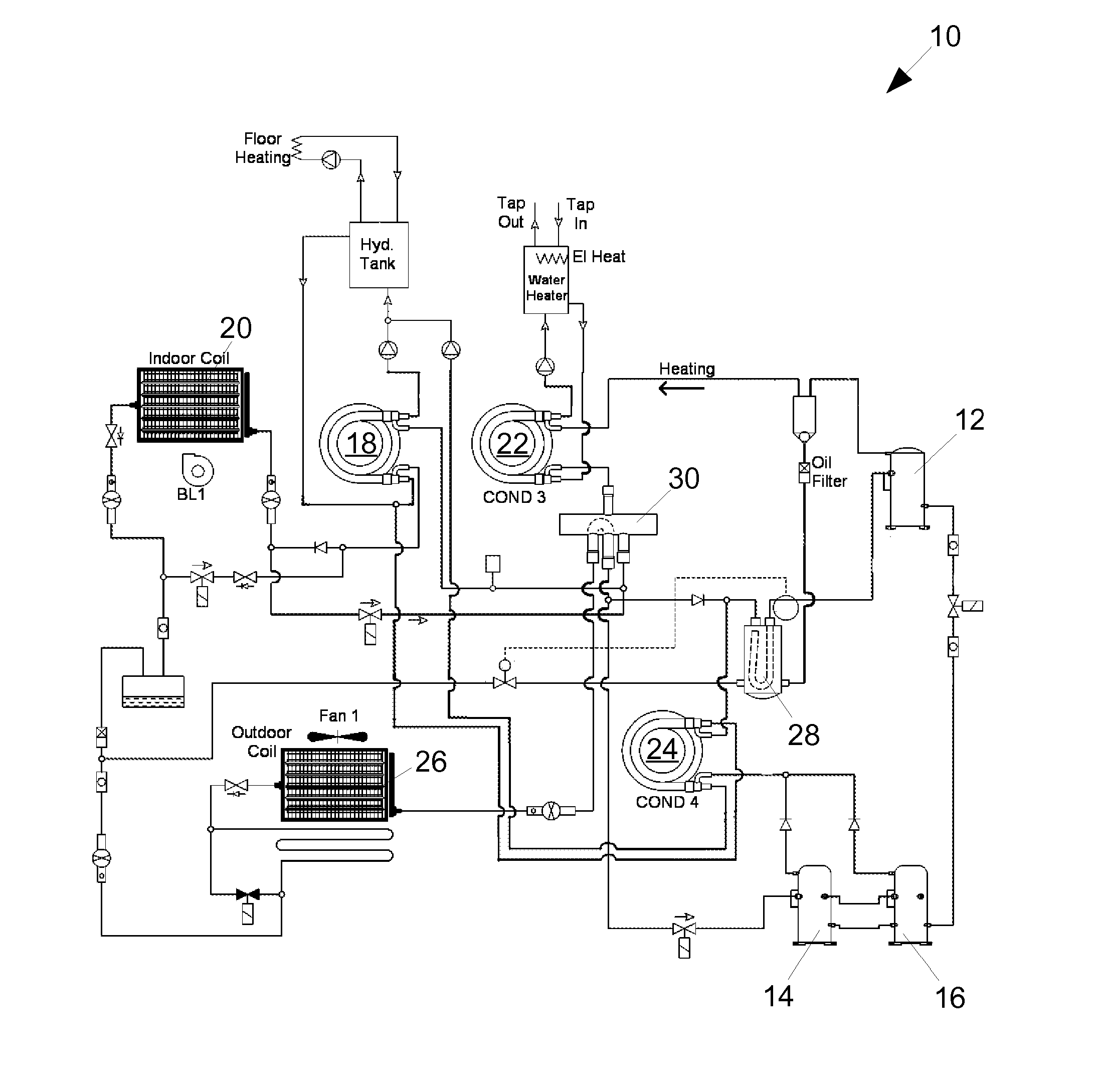
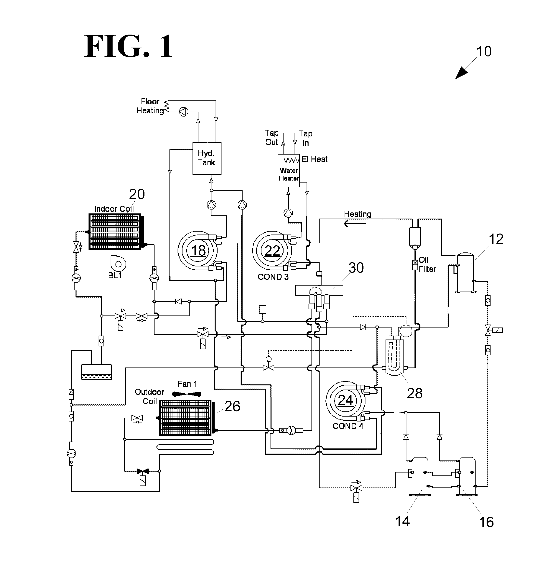
[0065]FIG. 1 is a schematic of the preferred embodiment of the heating and cooling system 10 of the present invention. The primary components of the system include a primary compressor 12, a first booster compressor 14, a second booster compressor 16, a hydronics condenser 18, a indoor air heat exchanger 20, a water tank condenser 22, a boost condenser 24, an evaporator 26, an accumulator 28, and a 4-way valve 30.

[0066] The primary compressor 12 is preferably a scroll-type two-speed compressor that may be operated at two discrete discharge pressure settings. The first and second booster compressors (14 and 16) are preferably single-speed compressors of varied discharge capacities that may be operated at a single discharge pressure setting. The primary compressor may be operated in series with the booster compressors operating in parallel. One or both of the booster compressors (14 and 16) may be bypassed.

[0067] In heating and cooling modes, compressed refrigerant fr...


PUM


Abstract

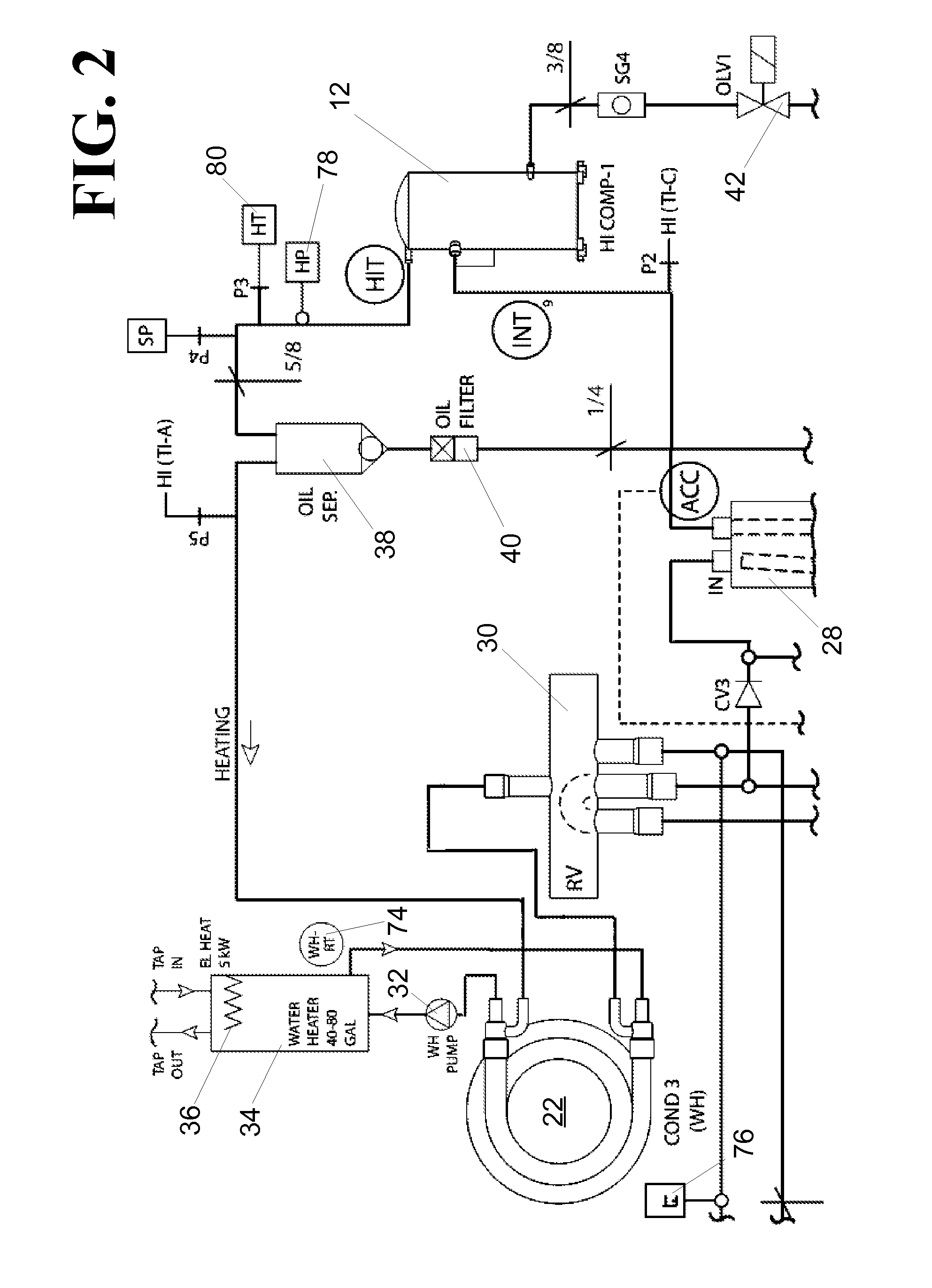
A heat pump system is disclosed that utilizes an accumulator fluidly connected between a boost compressor output and a primary compressor input. The accumulator is multifunctional in that it allows the refrigerant from the boost compressor to be cooled with refrigerant from other parts of the system if necessary. The accumulator also serves to receive and cool the oil separated from the refrigerant near the output of the primary compressor. A method for distributing oil among the compressors is also disclosed.

Description

CROSS-REFERENCE TO RELATED APPLICATIONS [0001] This application is a Continuation-in-Part of application Ser. No. 11 / 589,621 entitled “Heat pump system and controls” filed Oct. 30, 2006, a Continuation-in-Part of application Ser. No. 11 / 126,660 entitled “Heating / Cooling System” filed May 11, 2005 that claims priority to Provisional Application Ser. No. 60 / 570,402 entitled “Heat pump” filed May 12, 2004, the contents of which are all incorporated herein by reference.FIELD OF THE INVENTION [0002] The present invention relates generally to heating and cooling systems and more specifically to a heating and cooling system with multiple compressors, multiple heat outputs, and the control system for managing the system. BACKGROUND OF THE INVENTION [0003] Heat pump systems have found widespread application for heating and cooling homes and businesses. Because heat pump systems utilize the same primary components for both heating and cooling, they eliminate the need for separate heating and ...

Claims


Application Information

Patent Timeline
Patent Type & Authority Applications(United States)
IPC IPC(8): F25B5/00B60H1/32F25B7/00F25B49/02F24D3/12F25B9/00F25B13/00F25B27/00
CPCF24D3/12F25B2700/21161F25B9/008F25B13/00F25B29/003F25B40/04F25B47/025F25B2309/061F25B2313/003F25B2313/008F25B2313/02321F25B2313/02334F25B2313/0234F25B2313/02741F25B2313/0314F25B2339/047F25B2400/0401F25B2400/0403F25B2400/13F25B2600/0252F25B2600/0253F25B2600/2509F25B2600/2511F25B2700/1931F25B2700/2104F25B2700/2106F25B2700/21152F25B1/10Y02B30/00
Inventor SEEFELDT, WILLIAM J.
Owner ELECTRO IND
Learn More