Agricultural implement with automatic shank depth control

a technology of agricultural implements and depth control, which is applied in the direction of agricultural lifting devices, agricultural machines, adjusting devices, etc., can solve the problems of increasing fuel consumption, unnecessarily increasing the wear on the shank, and reducing yield, so as to accurately determine the location of soil compaction layers and accurately determine the shank point of soil compaction

Active Publication Date: 2019-01-15
CNH IND CANADA
View PDF18 Cites 36 Cited by
  • Summary
  • Abstract
  • Description
  • Claims
  • Application Information

AI Technical Summary

Benefits of technology

[0011]An advantage of the present invention is the controller can determine the location of a soil compaction layer using information obtained from the shank point breaking apart the soil.
[0012]Another advantage is the controller can accurately determine the location of a soil compaction layer using additional inputs such as shank point depth.
[0013]Yet another advantage is the controller can obtain feedback from the shank point to accurately determine the soil breaking behavior of the shank point and adjust the depth of the shank point appropriately.

Problems solved by technology

When the roots of many crops spread out at the boundary, the crop roots all compete for nutrients in a relatively limited volume of soil, decreasing yield.
The increased resistance of the soil to the implement advancing requires greater fuel consumption and also unnecessarily increases the wear on the shank.
One particular problem with this method is that it is time-consuming and the compaction layer may not be uniform throughout a field, requiring the farmer to sample many locations throughout the field to determine where the compaction layer(s) exist and what the depths are at each location.

Method used


Image

  • Agricultural implement with automatic shank depth control
  • Agricultural implement with automatic shank depth control
  • Agricultural implement with automatic shank depth control

Examples


Embodiment Construction

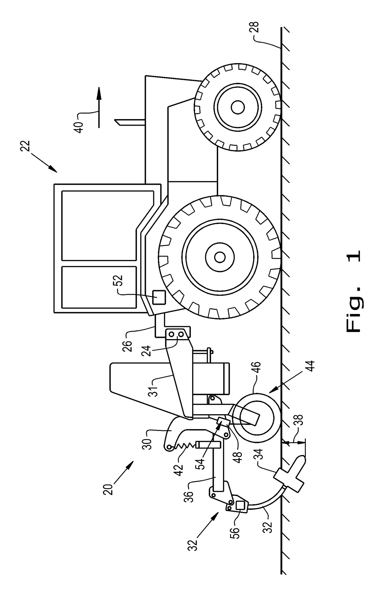
[0026]Referring now to the drawings, and more particularly to FIG. 1, an embodiment of an agricultural implement 20 formed according to the present invention is shown. The implement 20 is designed to be towed behind a work vehicle, such as the illustrated tractor 22. In the illustrated embodiment, the implement 20 includes a hitch 24 configured to attach to an appropriate tractor hitch assembly 26. As discussed in detail below, the tractor hitch assembly 26 may be adjustable to enable an operator and / or an automated system to vary a height of the implement 20 relative to a soil surface 28 on which the tractor 22 and implement 20 are traveling. As illustrated, the hitch 24 is coupled to an implement frame 30 which is carried by a chassis 31 of the implement 20 and configured to support multiple ground engaging tools, such as the illustrated shank 32. In the illustrated embodiment, the shank 32 includes a shank point 34 configured to break apart soil and a support arm 36. The shank po...


PUM


Abstract

An agricultural implement includes a chassis; an implement frame carried by the chassis; a shank connected to the implement frame, the shank including a shank point configured to break apart soil and a load sensor associated with the shank point which is configured to output shank load signals as the shank point advances through soil; an actuator carried by the chassis and configured to adjust a depth of the shank point; and a controller electrically coupled to the load sensor and the actuator. The controller is configured to receive the shank load signals; generate a load profile from the received shank load signals; analyze the load profile to determine whether the shank point is in a soil compaction layer; and activate the actuator to adjust the depth of the shank point based on the analyzed load profile.

Description

BACKGROUND OF THE INVENTION1. Field of the Invention[0001]The present invention relates to agricultural implements, and, more particularly, to agricultural implements equipped with shanks.2. Description of the Related Art[0002]Farmers utilize a wide variety of tillage implements to prepare soil for planting. Some such implements include two or more sections coupled together to perform multiple functions as they are pulled through fields by a tractor. For example, a field cultivator is capable of simultaneously tilling soil and leveling the tilled soil in preparation for planting. A field cultivator has a frame that carries a number of cultivator shanks with shovels at their lower ends for tilling the soil. The field cultivator converts compacted soil into a level seedbed with a consistent depth for providing excellent conditions for planting of a crop. Grass or residual crop material disposed on top of the soil is also worked into the seedbed so that it does not interfere with a see...

Claims


Application Information

Patent Timeline
Patent Type & Authority Patents(United States)
IPC IPC(8): A01B63/114A01B63/28
CPCA01B63/28A01B63/114
Inventor KOVACH, MICHAEL G.BARRICK, CHRISTOPHERHENRY, JAMES W.MEINERS, TRACEY D.
Owner CNH IND CANADA
Why Eureka
Try Eureka