
Heat exchanger

a heat exchanger and plate type technology, applied in indirect heat exchangers, laminated elements, light and heating apparatus, etc., can solve the problems of affecting the physical comfort of the vehicle passengers, the inability of the air conditioning of the motor vehicle to operate and provide a cooling capacity, and the rise in the interior temperature of the vehicle, so as to reduce the complexity, reduce the cost, and the effect of simple manufacturing

Inactive Publication Date: 2019-01-15
MAHLE INT GMBH
View PDF25 Cites 0 Cited by
  • Summary
  • Abstract
  • Description
  • Claims
  • Application Information

AI Technical Summary

Benefits of technology

[0011]It is therefore an object of the invention to provide a heat exchanger, which is simple to manufacture and results in lower costs than the heat exchangers known in the conventional art at a simultaneously reduced complexity and reduced rejection rate.
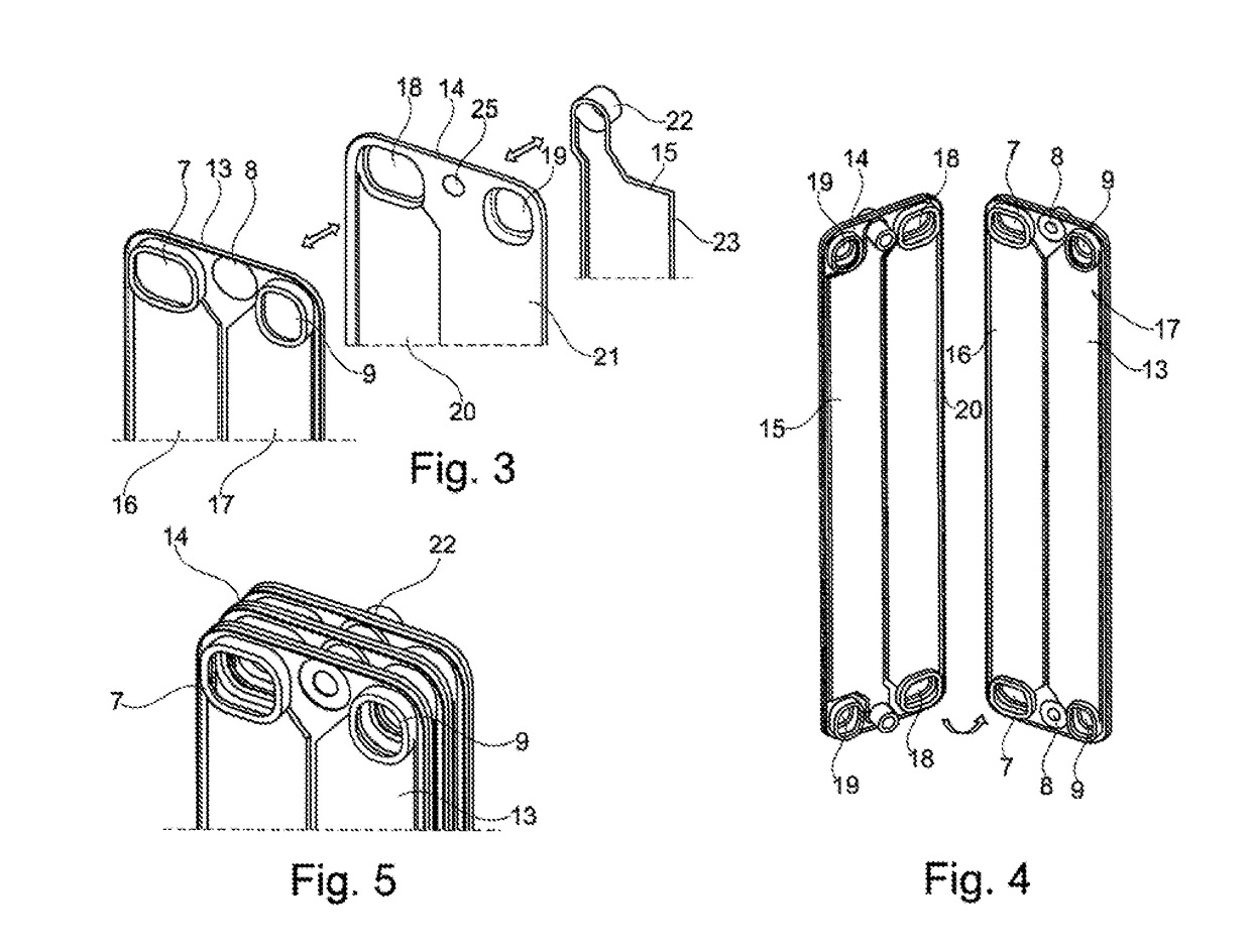
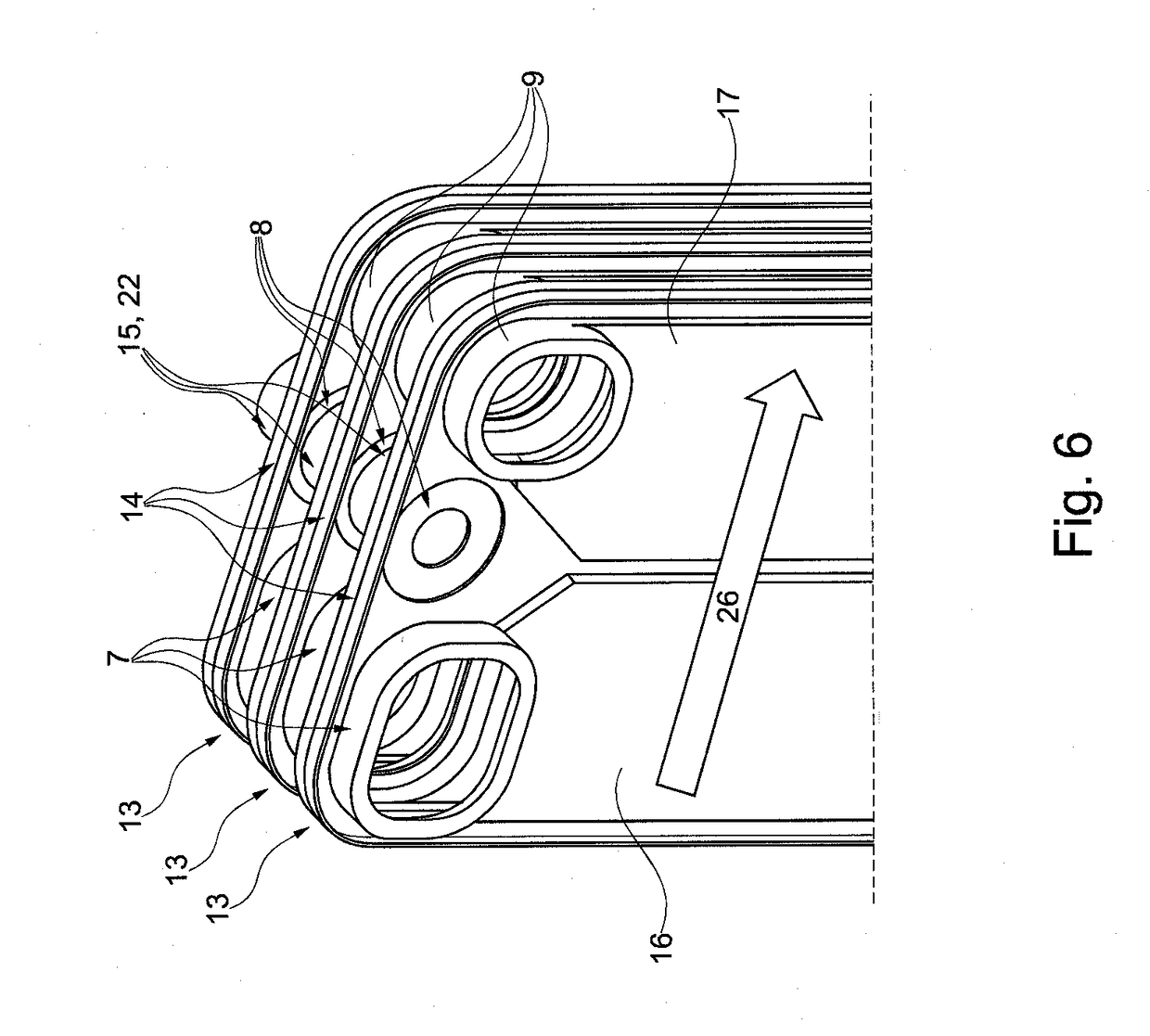
[0014]The first plate of the plate group at two opposite end regions can have two connecting regions each as an inlet and / or outlet of the first and second flow path and a channel-forming structure is provided between each of the two connecting regions to form the first and second flow path, whereby, furthermore, two openings and / or cups are provided at opposite ends of the first plate for connection to the third flow path. A rectangular plate, for instance, is provided with two short and two long sides, whereby then advantageously the particular connecting regions of the first plate are arranged on the two opposite short sides. In this regard, the flow paths of the first and second structures formed as flow paths would then be directed, for instance, in the direction of the long sides. As a result, a relatively long first and second flow path for the flowing fluid, such as for the refrigerant, can be created and a shorter fourth flow path for the air. This reduces the pressure drop for air and the noise of the air in the evaporator.
[0016]Also, no channel-forming structure or a volume-modified or reduced channel-forming structure can be formed between the two connecting regions of the second or first flow path. This is advantageous, so that the third flow path can be disposed in this region, without there being highly interfering effects of the first or second flow path.
[0017]A third plate can be connected to the second plate such that it is arranged in the plate region without a channel-forming structure or with a modified or reduced channel-forming structure and forms the third flow path and has openings and / or cups, which communicate with the openings and cups of the third flow path of the second plate as an inlet or outlet. This is advantageous because the third flow path can then be disposed in this region, without there being interfering effects of the first or second flow path.

Problems solved by technology

With a turned-off engine in the start-stop operation, the air conditioning of the motor vehicle can therefore no longer operate and provide a cooling capacity for cooling the vehicle's interior.
For one thing this causes the interior vehicle temperature to rise and to affect the physical comfort of the vehicle passengers negatively.
In the case of the active start-stop operation, the dehumidification of the air entering the vehicle interior can thus no longer be sufficiently assured, so that the humidity in the vehicle interior increases during the active start-stop operation.
This also results in an increase in humidity which is perceived as unpleasant and uncomfortable by the vehicle passengers.
However, in the conventional art, the corresponding production process is very complex and expensive, because many different parts have to be matched, joined, and calibrated in order to be able to produce a properly functioning heat exchanger.
In particular, a double tube with covered tube entries proves to be relatively complex, the number of parts is very high with at the same time a high number of different parts and compliance with tolerances represents a risk for process capability due to the many structural parts.
This in turn means an increased risk of leakage, so that apart from the parts costs the risk of the reject rates also increases.

Method used


Image

  • Heat exchanger
  • Heat exchanger
  • Heat exchanger

Examples


Embodiment Construction

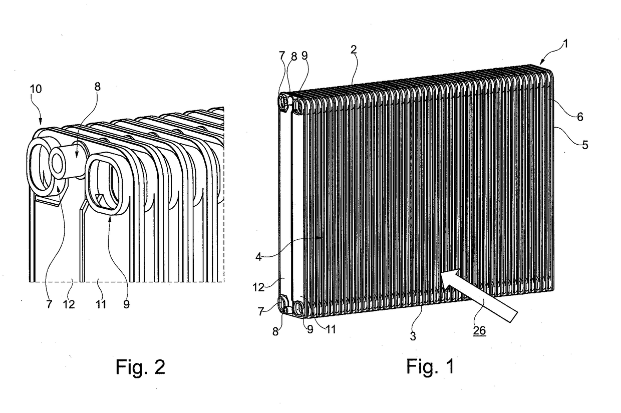
[0041]FIG. 1 shows a heat exchanger 1 with a first top header 2 and a second bottom header 3, which are arranged at two opposite ends of the heat exchanger and extend in a transverse direction, and having a block 4, in which the block network includes plates that are joined together to form plate groups, a plurality of plate groups 5 being arranged next to one another in order to form the heat exchanger network. Spatial regions 6, which are used for the flow of air through the heat exchanger, for example, are provided between two adjacent plate groups 5. The air flow direction is indicated by arrow 26. Fins such as, for example, corrugated fins can also be provided in the indicated spatial regions to improve the heat transfer.

[0042]It is evident that the top and bottom headers have substantially three flow channels, which are indicated by the three connecting pieces 7, 8, 9. These flow channels of the header extend in the transverse direction at the top side and at the bottom side o...


PUM


Abstract

A plate-type heat exchanger, in particular for motor vehicles, is provided that includes a plurality of plate groups in order to form first and second and / or third flow paths, a spatial region for fourth flow paths being formed between adjacent plate groups, the plate groups having at least one plate pair having a first and second plate in order to form the first flow paths and the second flow paths, wherein a third plate can be arranged in interaction with one of the first or one of the second plates in order to form the third flow path.

Description

[0001]This nonprovisional application is a continuation of International Application No. PCT / EP2012 / 076855, which was filed on Dec. 21, 2012, and which claims priority to German Patent Application No. 10 2011 090 159.0, which was filed in Germany on Dec. 30, 2011, and which are both herein incorporated by reference.BACKGROUND OF THE INVENTION[0002]Field of the Invention[0003]The invention relates to a plate-type heat exchanger, particularly for motor vehicles, with a plurality of plate groups to form first and second and / or third flow paths, whereby a spatial region for the fourth flow paths is formed between adjacent plate groups.[0004]Description of the Background Art[0005]Heat exchangers are provided in motor vehicles in a wide variety and for a multitude of different purposes. Thus, evaporators are used in climate control systems in order to cool the air by evaporation of the refrigerant in flow paths flowing through the evaporator, in order to bring about an air conditioning an...

Claims


Application Information

Patent Timeline
Patent Type & Authority Patents(United States)
IPC IPC(8): F28D9/00F28D20/02F28F3/00F28D1/03F28D1/04F28D21/00F28D20/00
CPCF28D9/0062F28D1/0333F28D1/0435F28D9/00F28F3/00F28D20/02Y02E60/145F28D2020/0013F28D2021/0085Y02E60/14
Inventor SEEWALD, WOLFGANGVIEHRIG, FALKNEUMANN, EMIL
Owner MAHLE INT GMBH
Learn More