Telematic monitoring system for vehicles

a technology for monitoring systems and vehicles, applied in the direction of vehicles, pedestrian/occupant safety arrangements, instruments, etc., can solve the problems of long installation time of vehicles, easy improvement of known types of devices, and inability to meet the needs of users

Inactive Publication Date: 2019-01-15
META SYST
View PDF16 Cites 0 Cited by
  • Summary
  • Abstract
  • Description
  • Claims
  • Application Information

AI Technical Summary

Benefits of technology

[0017]The main aim of the present invention is to provide a telematic monitoring system for vehicles that enables to detect accurate and reliable information.
[0018]Another object of the present invention is to provide a telematic monitoring system for vehicles which is easy and quick to install.
[0019]Another object of the present invention is to provide a telematic monitoring system for vehicles which allows to overcome the mentioned drawbacks of the prior art within the framework of a simple, rational, easy, effective to use as well as affordable solution.

Problems solved by technology

These appliances of known type, however, are susceptible to improvements, aimed in particular to improve the quality and accuracy of the detected information.
Additionally, the installation of the appliance on the vehicle is often long and complex.

Method used


Image

  • Telematic monitoring system for vehicles
  • Telematic monitoring system for vehicles
  • Telematic monitoring system for vehicles

Examples


first embodiment

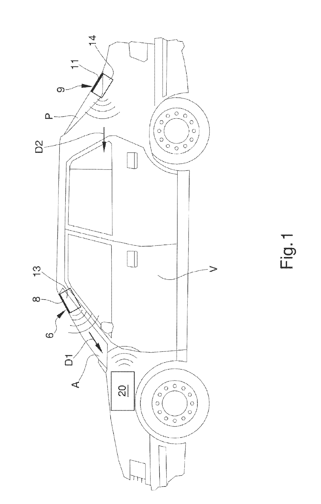
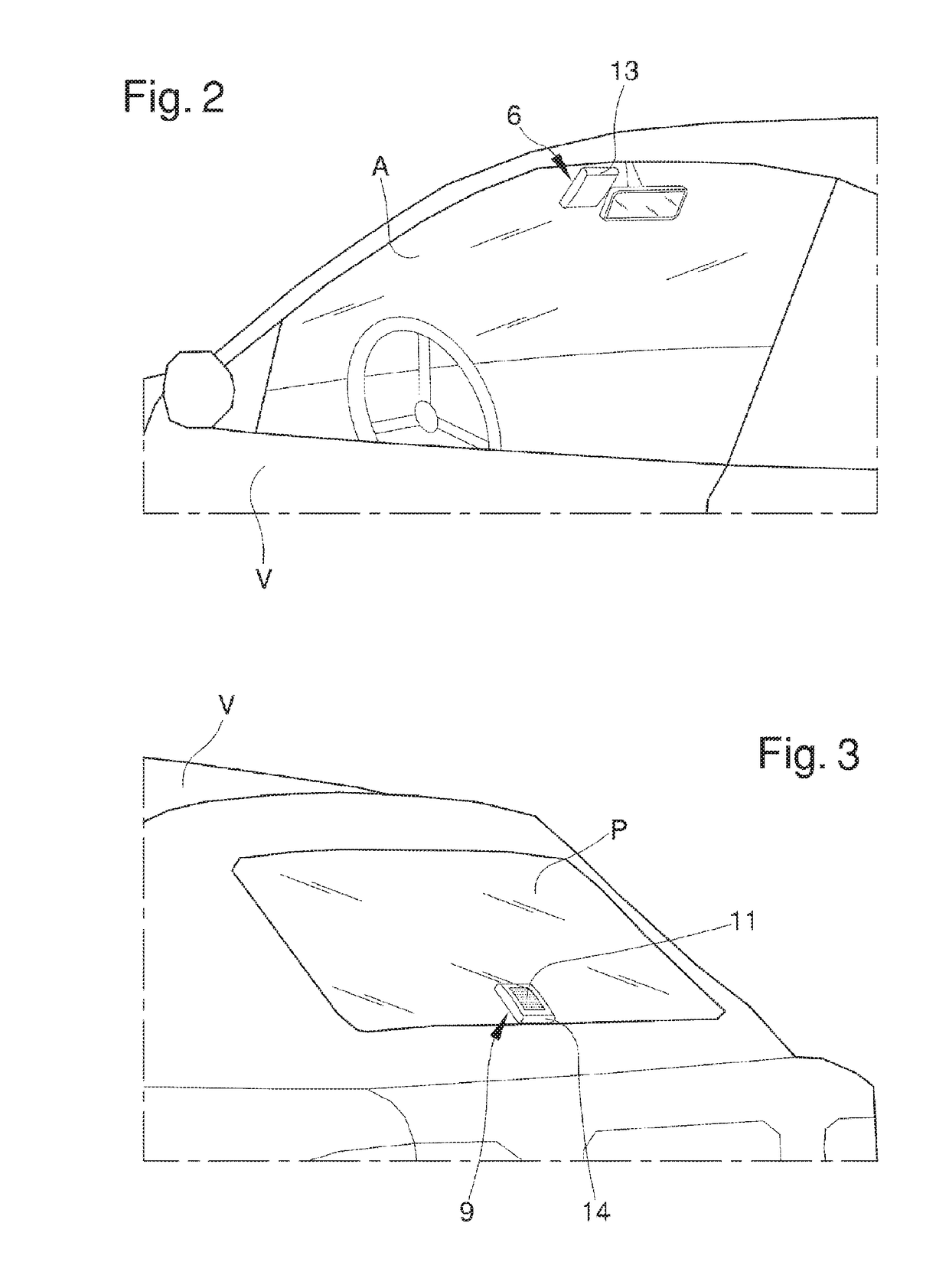
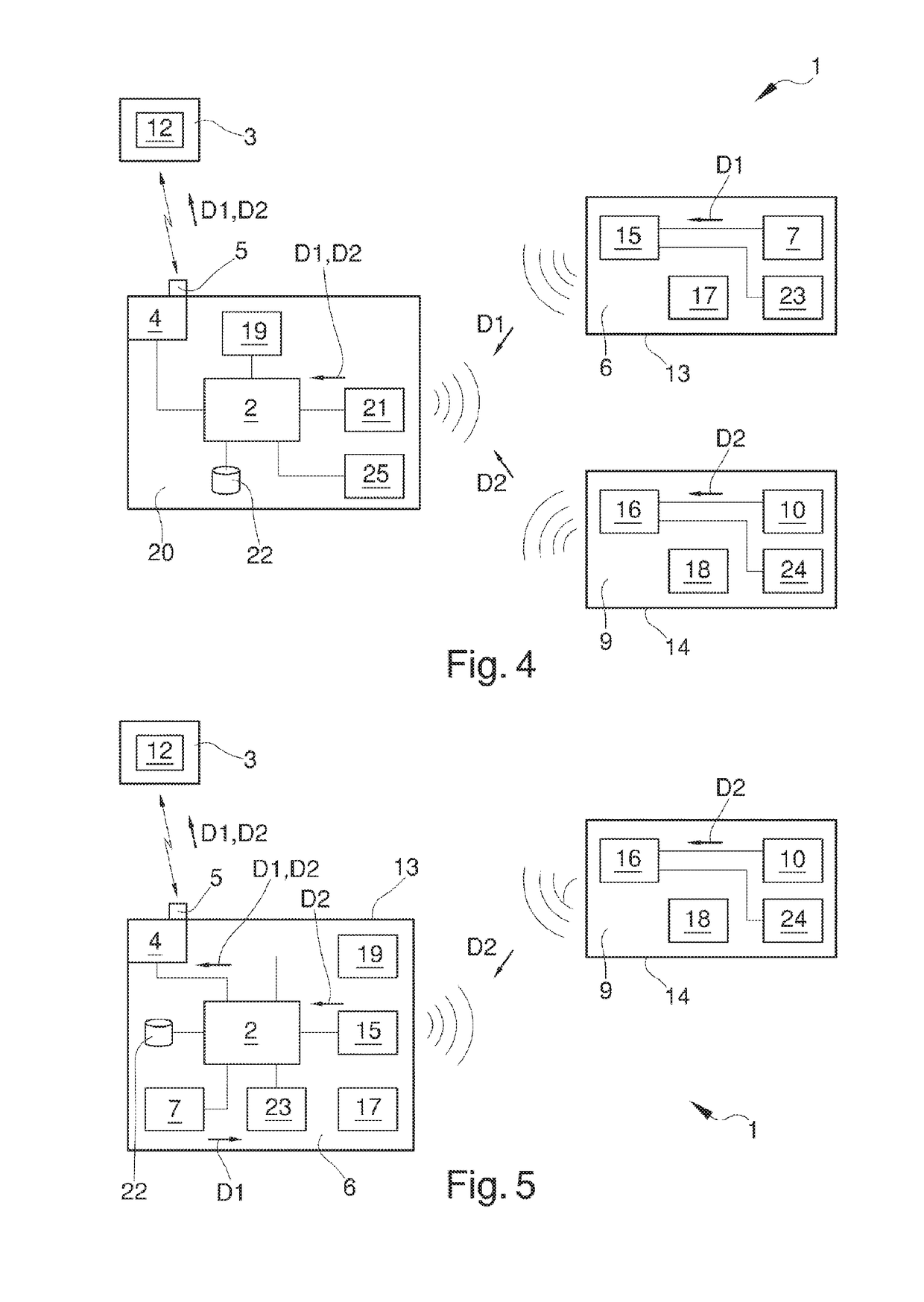
[0046]According to a possible first embodiment, schematically shown in FIG. 1 and in the diagram of FIG. 4, the system 1 comprises a local exchange 20 installable on board the vehicle V, having the management and control unit 2, the communication unit 4, the localization unit 19 and an additional third radio frequency transmission / receiving unit 21 able to transmit / receive radio frequency signals to / from the first and second devices 6 and 9.

[0047]Conveniently, the local exchange 20 can also have respective third measurement means 25 constituted by a third triaxial accelerometer.

[0048]Conveniently, according to a preferred solution, the local exchange 20 can be fastened to the electric battery of a vehicle V and can be electrically connected directly to the electric poles P+ and P− of the battery itself.

second embodiment

[0049]With reference to a possible second embodiment, schematically shown in FIG. 5, the management and control unit 2, the communication unit 4 and the localization unit 19 can be made integral within one of the devices 6 and 9 themselves (in the example illustrated in the figure within the first device 6).

[0050]In this way, the installation operations of system 1 on the vehicle are further simplified and can be performed quickly even by unskilled personnel.

[0051]Conveniently, the system 1 can comprise at least a storage unit 22 able to store the information relating to the vehicle V.

[0052]In particular, one or more storage units 22 can be integrated inside the local exchange 20, one or both devices 6 and 9 and / or the remote processing unit 3. Advantageously, the first device 6 and the second device 9 comprise first and second detection means 23 and 24 respectively, for detecting a bump on the front glass A and on the rear glass P.

[0053]In particular, said first and second detectio...


PUM


Abstract

The telematic monitoring system (1) for vehicles comprise a management and control unit (2) installed on a vehicle and capable of managing and controlling information relating to the vehicle (V) itself, a remote processing unit (3) for processing said information, a communication unit (4) installed on the vehicle (V), operatively connected to the management and control unit (2) and capable of communicating with the remote processing unit (3), a first device (6) operatively connected to the management and control unit (2), having first measurement means (7) for measuring instantaneous acceleration and first integral fastening means (8) to a front glass (A) of the compartment of the vehicle (V), a second device (9) operatively connected to the management and control unit (2), having second measurement means (10) for measuring instantaneous acceleration and second integral fastening means (11) to a rear glass (P) of the compartment of the vehicle (V), processing means (12) of first acceleration data (D1) and of second acceleration data (D2) coming from the first device (6) and from the second device (9) respectively, for the processing of the way a bump occurs on / of the vehicle (V).

Description

RELATED APPLICATIONS[0001]This application is a National Phase of PCT Patent Application No. PCT / IB2015 / 052972 having International filing date of Apr. 23, 2015, which claims the benefit of priority of Italian Patent Application No. MO2014A000113 filed on Apr. 24, 2014. The contents of the above applications are all incorporated by reference as if fully set forth herein in their entirety.FIELD AND BACKGROUND OF THE INVENTION[0002]The present invention relates to a telematic monitoring system for vehicles.[0003]Telematic appliances are known which, once installed on board a vehicle, are able to detect the modes of use of the vehicle itself over time.[0004]Such appliances find application, e.g. in the insurance field, for the determination of customized rates on the basis of the actual use of the vehicle, in the environmental field, for the real-time detection of the polluting emissions of a vehicle, or in the vehicle rental management, in order to achieve greater automation of proced...

Claims


Application Information

Patent Timeline
Patent Type & Authority Patents(United States)
IPC IPC(8): B60R21/0132B60T8/172G07C5/08G07C5/00
CPCG07C5/008G07C5/0816
Inventor SIMONAZZI, GIUSEPPE
Owner META SYST
Why Eureka
Try Eureka