System for determining positions with a sensor using a 2D-code pattern for determination of a discrepancy from an ideal situation

Active Publication Date: 2019-01-22
HEXAGON TECH CENT GMBH
View PDF23 Cites 0 Cited by
  • Summary
  • Abstract
  • Description
  • Claims
  • Application Information

AI Technical Summary

Benefits of technology

The present invention provides a better system for figuring out where a sensor is located in relation to a pattern. This system can measure both the deviation of the sensor from its ideal position and the precise position of the sensor.

Problems solved by technology

A disadvantage of systems with incremental position finding is that, when the system is restarted, it is necessary to start from a zero or reference position again each time.
In practice, however, undesirable deviations from this ideal situation frequently arise, i.e. the position of the sensor in relation to the pattern varies unintentionally often in at least one further spatial direction, i.e. in respect of at least one further degree of freedom of movement, e.g. in the form of an offset, a skew or a tilt.
In addition, skew or tilts in the sensor can arise, i.e. unintentional rotation of the sensor about at least one of its axes.
Such discrepancies from the ideal situation can adversely affect measurement accuracy.
Keeping such deviations as small as possible, i.e. observing the ideal position as accurately as possible, or compensating for deviations requires a high level of design complexity and / or complex calibration methods, particularly when there is a large region of movement in the direction of advance.
A disadvantage of the system according to U.S. Pat. No. 6,333,511 is that firstly absolute position finding is not possible, secondly it is not possible to determine further deviations from an ideal position for the sensor relative to the pattern other than a slight movement by the object or the sensor perpendicular to the direction of advance and a flush orientation of the sensor, and thirdly orientation of the detector array along the direction of advance, i.e. scanning in the direction of advance instead of orthogonally in relation thereto, is admittedly possible but is associated with losses of precision.
A disadvantage in this case is that the absolute position can be determined only relatively coarsely.

Method used


Image

  • System for determining positions with a sensor using a 2D-code pattern for determination of a discrepancy from an ideal situation
  • System for determining positions with a sensor using a 2D-code pattern for determination of a discrepancy from an ideal situation
  • System for determining positions with a sensor using a 2D-code pattern for determination of a discrepancy from an ideal situation

Examples


Embodiment Construction

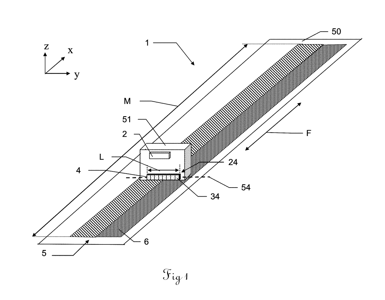
[0043]FIG. 1 shows a schematic overview of a system 1 according to the invention for determining positions along a direction of advance F in a perspective view. In addition, the three spatial axes x, y and z are shown. The direction of advance F corresponds to the x direction. The system 1 has a first two-dimensional pattern (abbreviation: 2D pattern) 5 comprising pattern elements 6 that is set on a pattern support 50. The system 1 is positioned such that the first 2D pattern 5 is situated in the xy plane and the longitudinal axis of the first 2D pattern 5 is the same as the x axis, so that the first 2D pattern extends in the direction of advance F. The system 1 additionally has a first scanning head 51 having a control and evaluation unit 2 and having a first sensor 4 for scanning the first 2D pattern 5, wherein the sensor 4 has a scanning length L that is known and stored in the control and evaluation unit 2. The scanning length L of the sensor 4 defines a longitudinal axis 54 of ...


PUM


Abstract

System for determining positions along a direction of advance, having a first sensor, particularly a line sensor, having a scanning length (L) for scanning a first 2D pattern and producing a scan signal. The first 2D pattern has pattern elements that each form a first code word on at least one portion of the scanning length (L), which first code word codes a position along the direction of advance absolutely. In addition, the first code word can be taken as a basis for determining a deviation from an ideal position for the first sensor in relation to the first 2D pattern.

Description

FIELD OF THE INVENTION[0001]Some embodiments of the invention relate to a system for determining positions along a direction of advance having a sensor for scanning a pattern and a scannable 2D and also to a method for determining positions along a direction of advance and just such a computer program product.BACKGROUND[0002]Systems for determining positions along a direction of advance are required in many fields of application in which the position of an object that is mobile along a direction of advance needs to be determined, e.g. the position of a machine component on a linear axle, such as drives or swivel arms. The positions sensed in this case can be used as position values for measurement purposes, or else for positioning components using a drive with a position control loop. Such position finding systems are accordingly found in devices such as coordinate measuring machines (CMM), geodetic devices, robot arms or hydraulic actuators. Such a system normally has a pattern and...

Claims


Application Information

Patent Timeline
IPC IPC(8): G01D5/347G01D5/244
CPCG01D5/34746G01D5/24476G01D5/2449G01D5/341
Inventor FRITSCH, ROBERTSIERCKS, KNUT
Owner HEXAGON TECH CENT GMBH
Why Eureka
Try Eureka