
Linearly polarized active artificial magnetic conductor

a magnetic conductor and linear polarization technology, applied in the direction of antennas, electrical equipment, etc., can solve the problems of excessive thickness and/or permeability, short circuit of antennas, and limited bandwidth of amcs, etc., to achieve reasonable amc bandwidth, and achieve the effect of reducing the thickness and/or permeability of amcs, and reducing the size of amcs

Active Publication Date: 2019-01-29
HRL LAB
View PDF67 Cites 5 Cited by
  • Summary
  • Abstract
  • Description
  • Claims
  • Application Information

AI Technical Summary

Benefits of technology

The present invention introduces an active artificial magnetic conductor that features a structure consisting of metallic patches arranged in a two-dimensional array. These patches have impedance elements that are connected to neighboring elements with non-Foster negative inductors. The structure also includes RF isolating plates between rows of unit cells to prevent cross coupling between the inductors. The impedance elements create an impedance to an incoming wave, which is represented by the grid admittance Yg. The technical effects of this invention include improved RF shielding, reduced interference, and improved magnetic conductivity.

Problems solved by technology

However these surfaces reflect electromagnetic waves out of phase with the incident wave, thus short circuiting the antennas.
But such AMCs have limited bandwidth.
At VHF-UHF frequencies, the thickness and / or permeability necessary for reasonable AMC bandwidth is excessively large for antenna ground-plane applications.
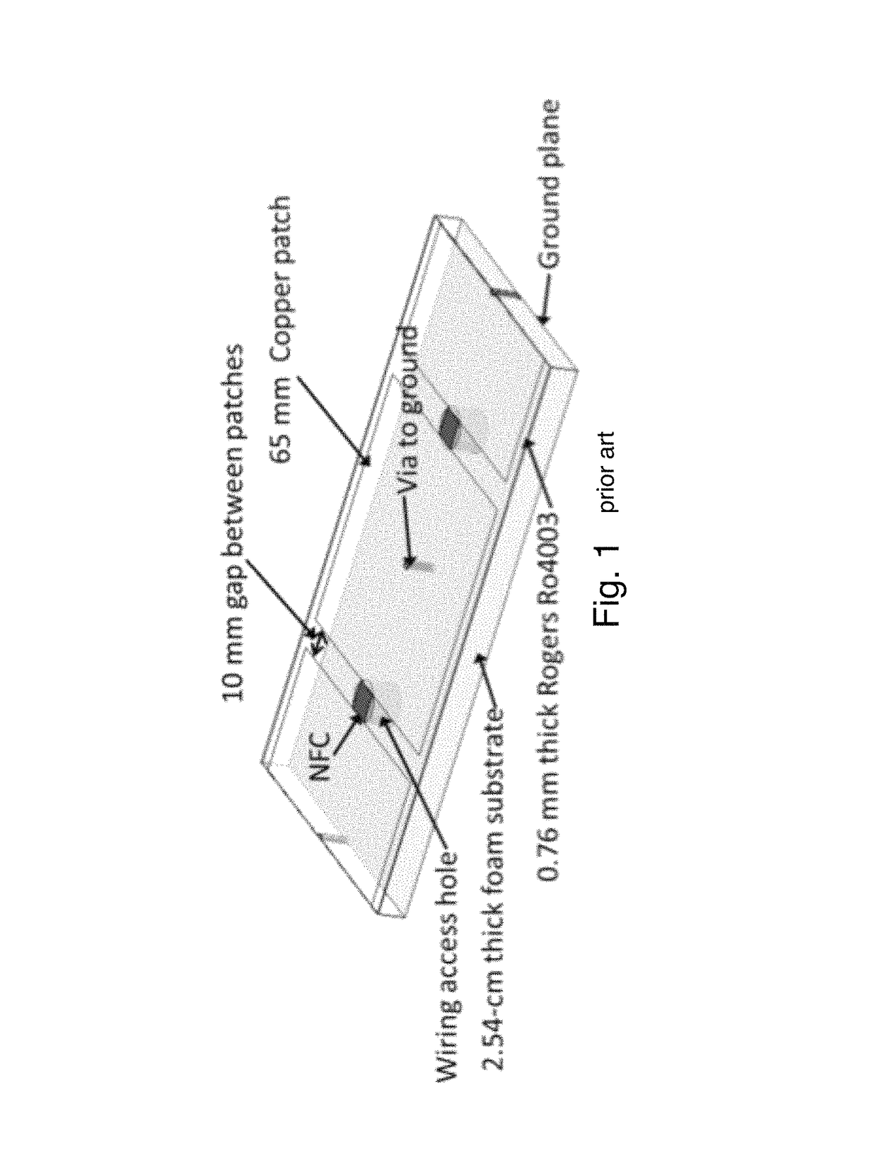
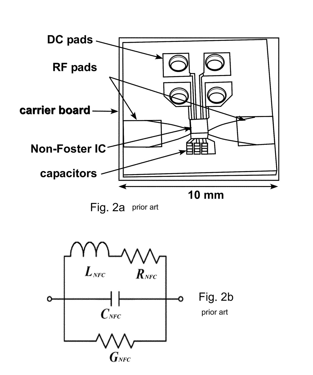
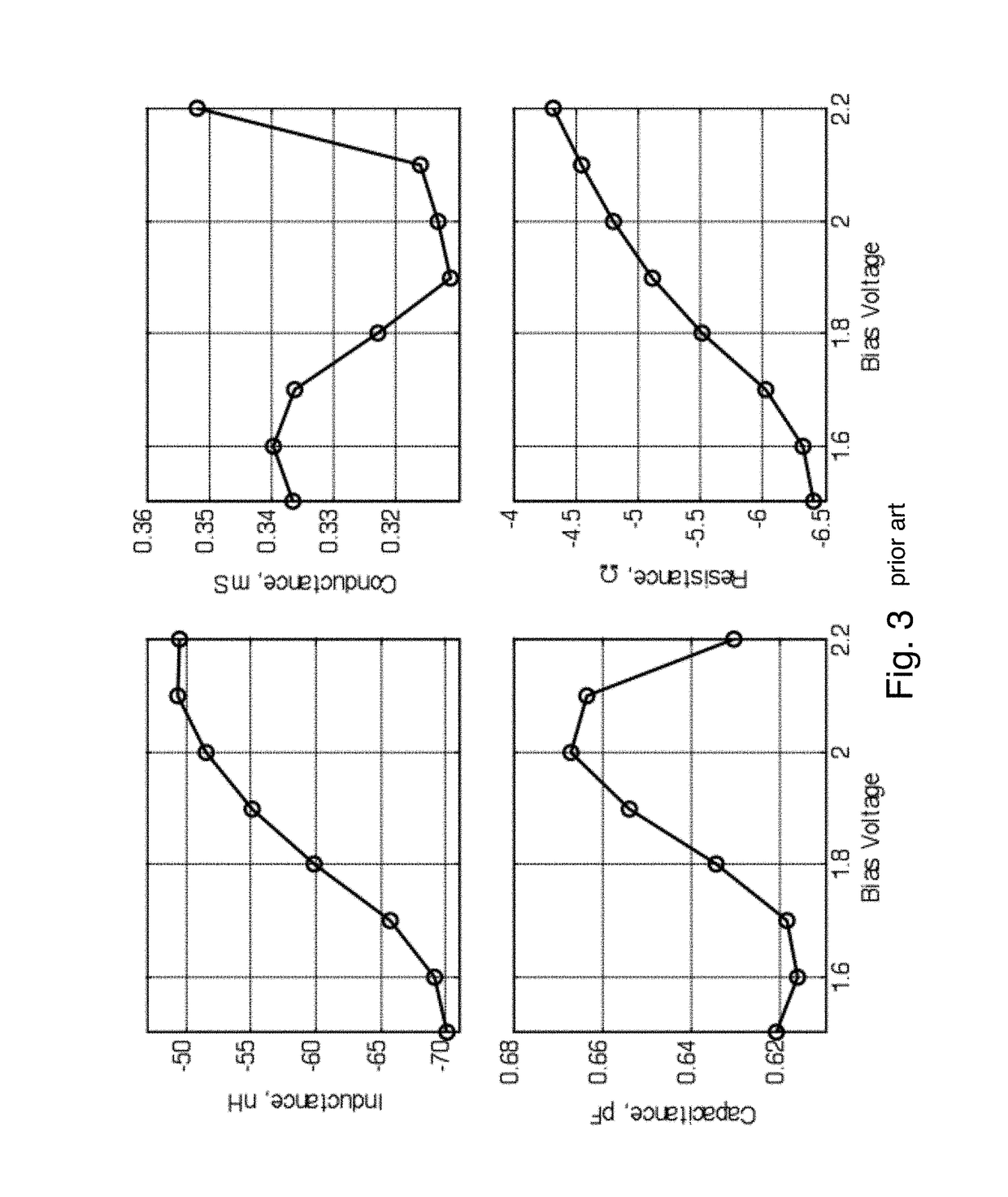
In U.S. Pat. No. 8,976,077 issued Mar. 10, 2015 and entitled “Wideband Tunable Impedance Surfaces”, a method of making an AAMC is described using Non-Foster Circuits (NFCs), but it does not disclose how to ensure stability of the AAMC itself which is due to the fact that it was discovered later that NFCs (which were designed with stability in mind) used in the AAMC resulted in instability due to cross coupling in the E-plane.
This instability is manifested as an uncontrolled oscillation of the NFCs and spurious emitted radiation.

Method used


Image

  • Linearly polarized active artificial magnetic conductor
  • Linearly polarized active artificial magnetic conductor
  • Linearly polarized active artificial magnetic conductor

Examples


Embodiment Construction

[0025]This invention comprises an AAMC having a plurality of unit cells 19, each unit cell 19 comprising a metallic patch 22 disposed spaced from a ground plane 24 by a substrate 28. See FIGS. 4a1 and 4a2. The metallic patch 22 of the cells 19 are connected to a metallic patch 22 of a neighboring cell 19 with non-Foster negative inductors 30 in one direction. The AAMC further has RF isolation plates 20 disposed or arranged within the substrate 28. These isolation plates 20 stabilize the AAMC by reducing the E-plane coupling between the negative inductors.

[0026]But before discussing the use of such isolation plates 20 to stabilize the AAMC it might be useful to first discuss the theoretical underpinnings of AMCs and AAMCs in general and how NFCs 30 may be implemented.

AMCs and AAMCs

[0027]An AMC is characterized by its resonant frequency, ω0, which is where an incident wave is reflected with 0° phase shift, and by its ±90° bandwidth, which is defined as the frequency range where the re...


PUM


Abstract

An active artificial magnetic conductor comprising an array of unit cells, each unit cell comprising an electrically conductive patch that is connected with an electrically conductive patch of neighboring unit cell in a column of unit cells using a non-Foster negative inductor and having RF isolating plates or walls between rows of unit cells. These isolating plates or walls eliminate undesirable cross coupling between the non-Foster negative inductors. The electrically conductive patches may be formed by metallic patches preferably arranged in the 2D array of such patches. Each patch preferably has a rectilinear shape.

Description

CROSS REFERENCE TO RELATED APPLICATIONS[0001]This application claims the benefit of U.S. Provisional Patent Application Ser. No. 62 / 051,778, filed Sep. 17, 2014 and entitled “Linearly polarized active artificial magnetic conductor”, the disclosure of which is hereby incorporated herein by reference.[0002]This application is related to (i) U.S. Pat. No. 8,976,077 issued Mar. 10, 2015 and entitled “Wideband Tunable Impedance Surfaces” and also to (ii) U.S. Pat. No. 8,988,173 issued Mar. 24, 2015 and entitled “Differential Negative Impedance Converters and Inverters with Tunable Conversion Ratios”, the disclosures of which are also incorporated herein by reference.TECHNICAL FIELD[0003]This invention relates an active artificial magnetic conductor (AAMC) which includes a periodic array of unit cells which reflects electromagnetic waves incident on its surface with zero-degree phase shift.BACKGROUND[0004]It is often desirable to place antennas near and parallel to metallic surfaces. Howe...

Claims


Application Information

Patent Timeline
IPC IPC(8): H01Q15/00H01Q15/14
CPCH01Q15/14H01Q15/008
Inventor GREGOIRE, DANIELWHITE, CARSONCOLBURN, JOSEPH
Owner HRL LAB
Learn More