Network topology system and method

a network topology and network topology technology, applied in the field of computer networks, can solve the problems of the complexity and the power consumption of the network system, so as to achieve the effect of not increasing the cost of the network system and simple structure of the whole network system

Active Publication Date: 2019-01-29
NAT CHENG KUNG UNIV
View PDF4 Cites 0 Cited by
  • Summary
  • Abstract
  • Description
  • Claims
  • Application Information

AI Technical Summary

Benefits of technology

[0006]In view of the foregoing problems, an objective of the present invention is to provide a network topology system and method, of which the topology mathematical calculation is, in a system having multiple nodes, finding a set of node connection rules for nodes and the number of connections between each node and other nodes, to make it possible to construct a network topology formed by all nodes according to the connection rules and the number of connections without using a switch, so that the structure of the whole network system becomes simple and there is no power consumption of the switch; therefore, the cost of the network system will not increase, and moreover, each node achieves the so-called Democratized Dimension through the same form of communication freedom (using the same set of connection rules) and making the number of connections of all the nodes very close.

Problems solved by technology

However, the greater the number of nodes is, the more the number of switches used, the number of layers of switches that use a fat tree structure will also increase, thus resulting in that the whole network system has a quite complicated structure and is power-consuming, and the cost of the network system will also increase.

Method used


Image

  • Network topology system and method
  • Network topology system and method
  • Network topology system and method

Examples


Embodiment Construction

[0025]In order to enable those of ordinary skill in the art to further understand the present invention, preferred embodiments of the present invention are listed below to describe constitution contents and effects to be achieved of the present invention in detail in conjunction with the accompanying drawings.

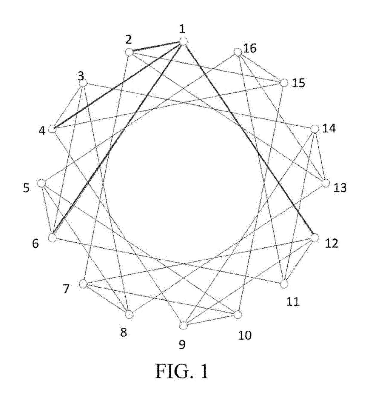
[0026]FIG. 1 is a schematic architectural diagram of nodes of a network topology system according to the present invention. In FIG. 1, the network topology system includes a plurality of nodes (node number 1, 2, . . . , 16), each node is a single core on chip, a processor, a computer, a group of internally optimized group of computers or a computational center, and for the nodes in the network topology system, connections are made between any starting node and the plurality of nodes node in the nodes according to a set of connection rules.

[0027]The embodiment of the present invention describes communication operations of the network topology system by taking 16 nodes as an exam...


PUM


Abstract

A network topology system comprises a plurality of nodes, each of the plurality of nodes having a set of connection rules which is built by the steps of: generating a series of prime number differences; generating a series of communication strategy numbers; extracting as many terms as the number of connecting nodes from a recursive sequences to serve as an index series; generating a series of connection strategy numbers by extracting the Nth terms from the series of communication strategy numbers, wherein N stands for each number of the index series; and generating a series of connecting nodes numbers by calculating the sum of each odd number and each term of the series of connection strategy numbers so as to build the connection rules for each odd-numbered node to connect the nodes numbered in corresponding with the numbers of the connecting nodes number series.

Description

BACKGROUND[0001]Technical Field[0002]The present invention relates to the technical field of computer networks, and in particular, to a network topology system and method.[0003]Related Art[0004]High-performance computers or computer systems can provide optimized use of hardware and software, which is achieved by using a processing node including one or more microprocessors and a memory. The computer systems are sometimes referred to as shared multiprocessor systems, and in a shared multiprocessor computer system, processors are regarded as network nodes for interconnection, enabling them to communicate with each other, to share an operating system, resources, data, memory and so on.[0005]In a parallel operation computer system, with increase of the number of computer nodes, network communication between the nodes will increase significantly, and in order to make the communication speed between every two nodes increase, it is possible to use a switch for communication between the nod...

Claims


Application Information

Patent Timeline
Patent Type & Authority Patents(United States)
IPC IPC(8): G06F15/173H04L12/24G06F15/80
CPCH04L41/12G06F15/17381G06F15/17387G06F15/803Y02D10/14H04L41/04H04Q2213/1304Y02D10/00
Inventor HWANG, CHI-CHUANLIANG, CHI-HSIUCHEN, YU-TIN
Owner NAT CHENG KUNG UNIV
Why Eureka
Try Eureka