Catheter

a catheter and catheter technology, applied in the field of catheters, can solve the problems of catheter blockage, patient discomfort, and a lot of discomfort, and achieve the effects of eliminating bladder wall damage, reducing trauma, and shortening the catheter above the balloon

Active Publication Date: 2019-02-05
THE FLUME CATHETER CO LTD
View PDF20 Cites 2 Cited by
  • Summary
  • Abstract
  • Description
  • Claims
  • Application Information

AI Technical Summary

Benefits of technology

[0020]The catheter design of the present invention, therefore, allows complete emptying of the bladder which will tackle the main factor influencing blockage. The balloon will retain the catheter in the bladder and the design has a missing half segment at the bottom where the drainage aperture is located. This allows complete bladder drainage while ensuring the aperture remains positioned at the base of the bladder. Since the hole is at the level of the balloon and not above it this means the length of catheter above the balloon can be shortened. This fact, combined with the inflatable tip, will both reduce trauma from the catheter tip to the bladder and also eliminate bladder wall damage from being sucked into the drainage hole. Catheter life, damage to the bladder wall and insertion difficulties will all be greatly improved with the catheter of the present invention.

Problems solved by technology

This urine tends to become infected and, through well understood processes, cause encrustations and catheter blockage.
This in turn leads to patient discomfort and bypassing of urine that then demands an urgent change of catheter when the whole process only starts again.
Some patients with chronic conditions have catheters that may only last a couple of weeks so over the years these individuals have to sustain a lot of discomfort with recurrent blockages and changes.
The clinical and financial problem is massive since there are currently 100 million catheters in use.
Another disadvantages of current catheter designs include damage or trauma to the bladder wall by the catheter tip, and damage to the bladder wall due to the bladder wall being sucked into the drainage hole, caused by the dome of the bladder collapsing over the drainage hole.

Method used


Image

  • Catheter
  • Catheter
  • Catheter

Examples


Embodiment Construction

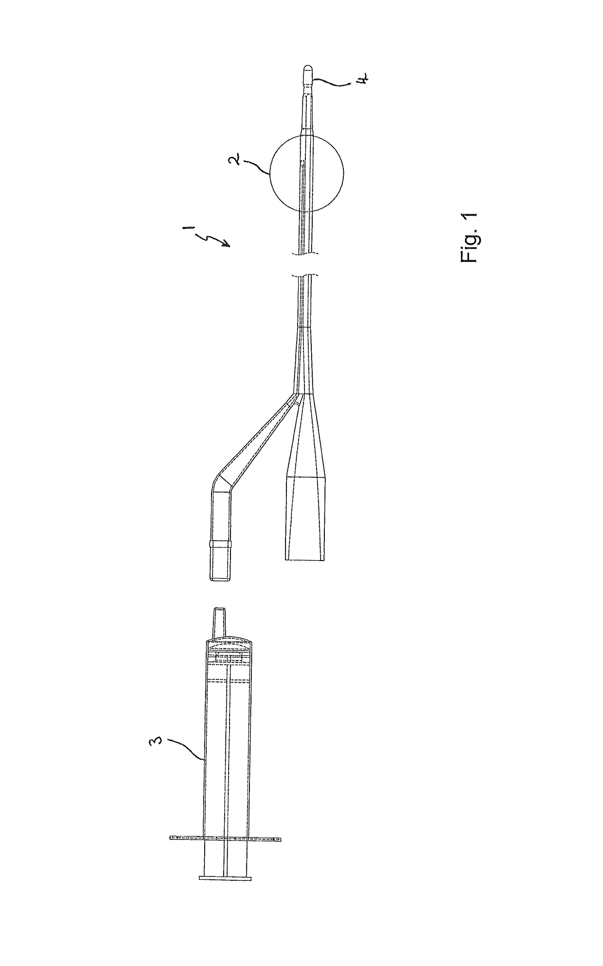
[0031]As shown in FIG. 1, it is known to provide catheters 1 with retention balloons 2 that function to retain the distal end 4 of the catheter 1 within a bladder during use. The catheters 1 may be supplied with a pre-filled water balloon or may use a syringe 3 to inflate the distal retention balloon. They are also made of differing materials but the spherical retention balloon2 is a common feature to them all.

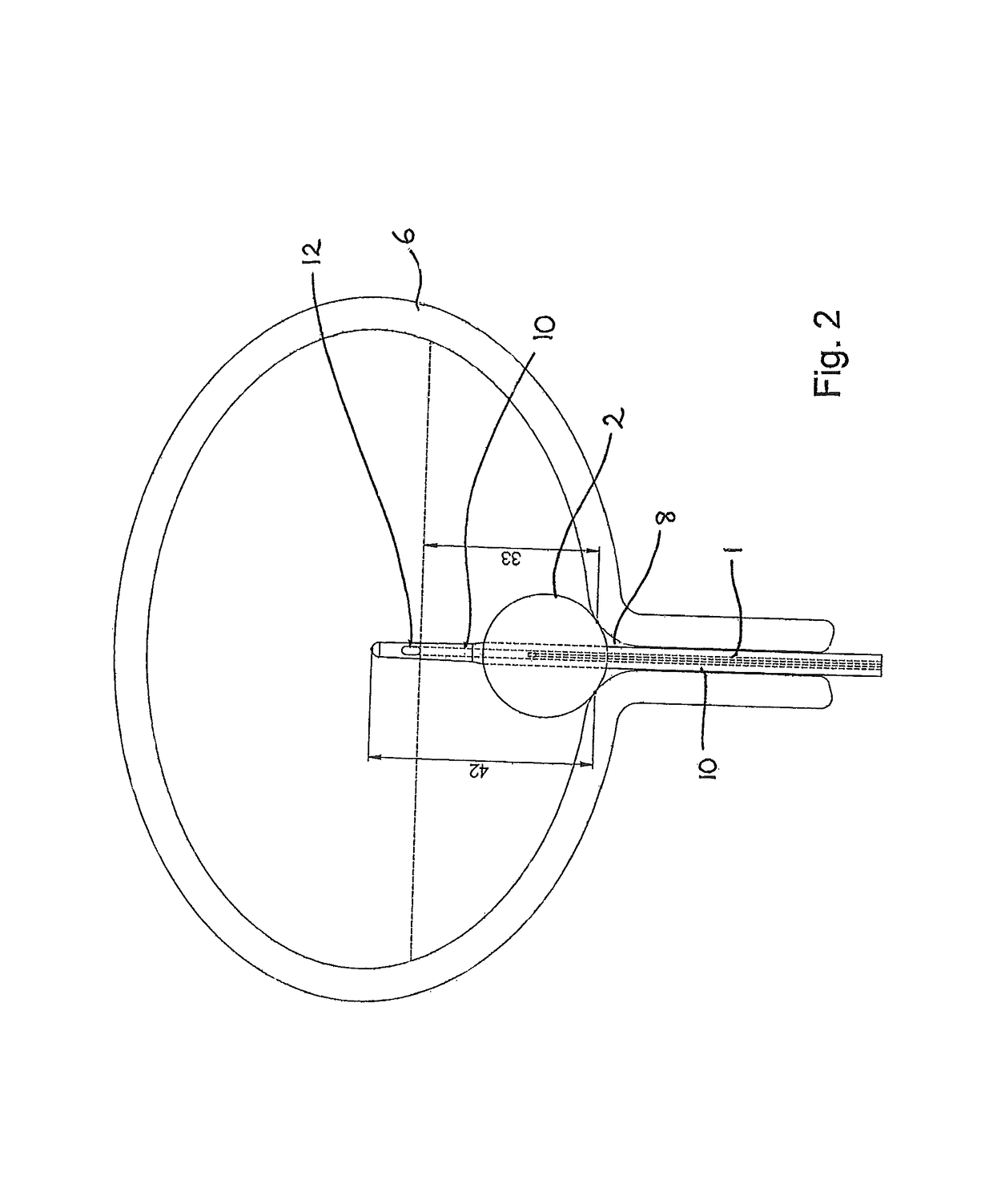
[0032]FIG. 2 illustrates a prior art catheter 1 inserted and functioning within a bladder 6. The balloon 2 sits over the urethral exit 8 from the bladder 6 and seals it along with the catheter tubing 10 itself. The drawing demonstrates that the bladder 6 can never empty because the drainage hole 12 sits approximately 33 mm into the bladder 6. This is the fundamental design flaw of current catheters, because stagnant urine remaining in the bladder encourages infection, commonly by Proteus Mirabilis. This then leads to the sequence of biofilm formation followed by crystal deposi...


PUM


Abstract

This invention relates to a catheter (220), and in particular to a urinary catheter. A catheter comprises an elongate shaft (222) having a longitudinal drainage bore (224) for conveying fluid along the shaft; an elongate, tapered tip portion (228) extending from an end of the shaft, the tip portion having a distal end (230) furthest from the shaft; a drainage aperture (232) provided in the tip portion, said aperture being in fluid communication with said bore; and an inflatable balloon element (236) attached to said tip portion, the balloon element being configured such that, when fully inflated, the balloon element fully surrounds the distal end of the tip portion and extends along the tip portion to a point on an opposite side of the drainage aperture to said distal end, a surface of the balloon element including a depression (242) providing a passageway in fluid communication with the drainage aperture.

Description

BACKGROUND[0001]a. Field of the Invention[0002]This invention relates to a catheter, and in particular to a urinary catheter.[0003]b. Related Art[0004]Current catheters have an inflatable balloon to keep the catheter in situ in the bladder and urine drainage apertures above the balloon and below the tip of the catheter.[0005]This means there remains residual urine in the bladder below the level of the drainage holes. This urine tends to become infected and, through well understood processes, cause encrustations and catheter blockage. This in turn leads to patient discomfort and bypassing of urine that then demands an urgent change of catheter when the whole process only starts again. Some patients with chronic conditions have catheters that may only last a couple of weeks so over the years these individuals have to sustain a lot of discomfort with recurrent blockages and changes. The National Health Service (NHS) in the United Kingdom or funding authorities over the world have to fu...

Claims


Application Information

Patent Timeline
Patent Type & Authority Patents(United States)
IPC IPC(8): A61M25/10A61M25/04A61M25/00
CPCA61M25/0017A61M25/007A61M25/04A61M25/1002A61M2025/1093A61M2025/0019A61M2025/107
Inventor HAVARD, JOHN SPENCER
Owner THE FLUME CATHETER CO LTD
Why Eureka
Try Eureka