Fouling mitigation in equipment used during hydrocarbon production

a technology for hydrocarbon production and equipment, applied in the direction of water/sludge/sewage treatment, chemical equipment and processes, hydrocarbons, etc., can solve the problems of heavy hydrocarbons that are difficult to recover or produce, various equipment can become contaminated or fouled, and the equipment can be contaminated or fouled. , to achieve the effect of reducing fouling, preventing or reducing fouling in equipment, and reducing fouling

Active Publication Date: 2019-02-05
CHAMPIONX LLC
View PDF13 Cites 0 Cited by
  • Summary
  • Abstract
  • Description
  • Claims
  • Application Information

AI Technical Summary

Benefits of technology

[0020]Methods for preventing or reducing fouling in equipment that contacts water used during a hydrocarbon production process are also disclosed. The methods can comprise the steps of adding to said water a composition comprising a silt dispersant and a hydrocarbon dispersant, dispersing one or more foulants contained in said water, thereby preventing fouling of the equipment, or dispersing one or more foulants deposited on said equipment, thereby reducing fouling of the equipment.

Problems solved by technology

However, heavy hydrocarbons can prove difficult to recover or produce due to their high viscosities.
Over time, recycled or reused water can become contaminated with silt, sand, clay, hydrocarbons, oil, grease, and other organic materials.
As this contaminated water is recycled through the various pieces of equipment used in connection with hydrocarbon recovery, the various pieces of equipment can become contaminated or fouled.
Since the water cannot be perfectly purified in the separation vessel, it can still contain certain impurities, such as silt, sand, clay, hydrocarbons, and other organic materials.
These impurities are carried with the water into the heat exchanger or other components of the system and the impurities can cause fouling of the various pieces of equipment.
If the recycled water passing through the heat exchanger has a high concentration of impurities, heavy fouling can occur.
Fouling of the heat exchangers can be very detrimental to the entire operation and can significantly limit and even stop production.
For example, from the beginning of the production or recovery process, it could take as little as two weeks for the heat exchanger to become significantly fouled such that it will need to be taken off-line and cleaned, and while it is being cleaned, production or recovery will come to a halt.
Currently, the industry deals with this problem by allowing the heat exchanger to become fouled to the point where either the flow of water is heavily restricted or no effective heat transfer is occurring between the water and the heat exchanger.
Although this can be a possible solution to the fouling problem, it requires a large amount of labor to manually clean out the fouled heat exchanger and it also requires a large amount of capital as at least two heat exchangers will need to be purchased.

Method used


Image

  • Fouling mitigation in equipment used during hydrocarbon production
  • Fouling mitigation in equipment used during hydrocarbon production

Examples


example 1

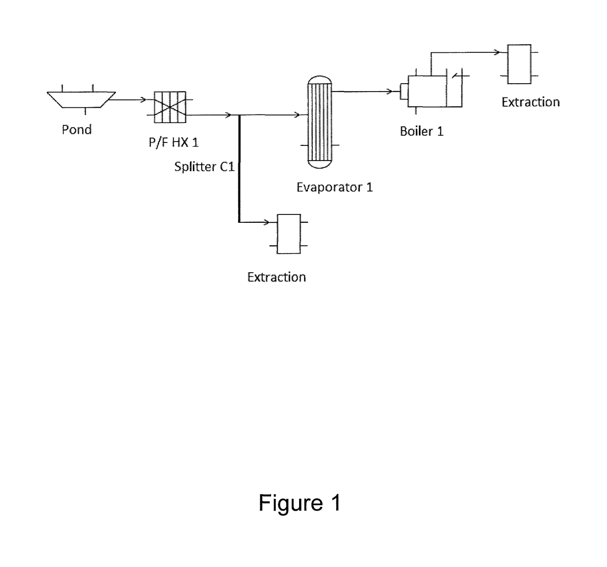
[0039]On both the tube side and the shell side of a heat exchanger being used in hydrocarbon recovery, extraction, or production, heavy tar-like deposits can accumulate. The deposits can have many different components and each component can comprise a different amount of the total deposit. For example, a deposit on the tube side can be from 45-55% sand and clay, 30-40% normal hydrocarbon (bitumen), and the remainder of the deposit can be 10-20% insoluble organics, such polar organics or organic salts, which might be a combination of naphthenates and demulsifier chemicals (such as esters and / or oxyalkylates).

[0040]With this information in mind, the present inventors performed laboratory studies to find a dispersant composition or solution to mitigate fouling. However, since the same water contacting the tube side of the exchanger could also contact the shell side of the exchanger, the results depicted below would be equally applicable to the shell side of the heat exchanger, the tube...

example 2

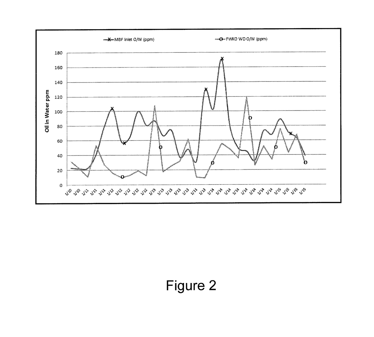
[0069]As can be seen in FIG. 2, example 2 supports the fact that aspects of the presently disclosed dispersants can actually clean any existing deposits or fouling on the equipment being used in the system. In example 2, Dispersant 3 was used, which is a 50 / 50 mixture of 1) a terpolymer of acrylic acid, acrylamide, and sulfonated acrylamide, and 2) ethoxylated phenol. Dispersant 3 was injected at a dose of 2.5 mg / L, directly into the outlet of the free water knock out (FWKO) which is located before the micro bubble flotation (MBF) tank. The rise in the oil in water, as can be seen in FIG. 2, going to the MBF inlet was the biggest indication that existing deposits of oil from the pipes was being cleaned. From the FWKO feed to the MBF tank inlet there is a large oil in water increase indicating oil removal from the pipe walls. This is also supported by an increase in turbidity indicating cleaning of the existing deposit containing both oil and silt. Thus, the presently disclosed dispe...


PUM

PropertyMeasurementUnit
lengthaaaaaaaaaa
temperaturesaaaaaaaaaa
temperatureaaaaaaaaaa

Abstract

Methods for dispersing foulants are disclosed herein. Various effective dispersant compositions are also disclosed. The dispersant composition can include a silt dispersant and a hydrocarbon dispersant. Generally, the silt dispersant can be a homopolymer or a copolymer of one or more monomers, and the monomers can be one or more of acrylic acid, methacrylic acid, α-halo acrylic acid, maleic acid, itaconic acid, vinyl acetic acid, allyl acetic acid, fumaric acid, β-carboxylic acrylate, and their salts. The silt dispersant can also be a terpolymer of acrylic acid, acrylamide, and sulfonated acrylamide. The hydrocarbon dispersant can be a non-ionic surfactant or a nonylphenol or a nonylphenol ethoxylate, such as a high EO 9 Nonyl phenol resin. Also disclosed are methods for preventing or reducing fouling in equipment that contacts water used during a hydrocarbon production process.

Description

CROSS-REFERENCE TO RELATED APPLICATIONS[0001]Not applicable.STATEMENT REGARDING FEDERALLY SPONSORED RESEARCH OR DEVELOPMENT[0002]Not applicable.THE NAMES OF THE PARTIES TO A JOINT RESEARCH AGREEMENT[0003]Not applicable.REFERENCE TO A SEQUENCE LISTING, A TABLE, OR A COMPUTER PROGRAM[0004]Not applicable.BACKGROUND OF THE INVENTION[0005]1. Field of the Invention[0006]The disclosure pertains to fouling mitigation in equipment used during hydrocarbon production. In particular, the disclosure pertains to compositions useful for the mitigation of oil, hydrocarbon, silt, insoluble organics, and precipitated inorganic minerals fouling in equipment used during hydrocarbon production, such as heat exchangers.[0007]2. Description of the Related Art[0008]When crude oil or bituminous sands are located sufficiently below the surface of the earth, oil wells can be drilled to assist in the extraction of these materials. However, heavy hydrocarbons can prove difficult to recover or produce due to the...

Claims


Application Information

Patent Timeline
Patent Type & Authority Patents(United States)
IPC IPC(8): C02F5/10C02F1/68C02F103/36
CPCC02F1/682C02F5/10C02F2103/365
Inventor GILL, JASBIR SMAHARAJH, EDWARDMILLER, THOMAS M.
Owner CHAMPIONX LLC
Why Eureka
Try Eureka