

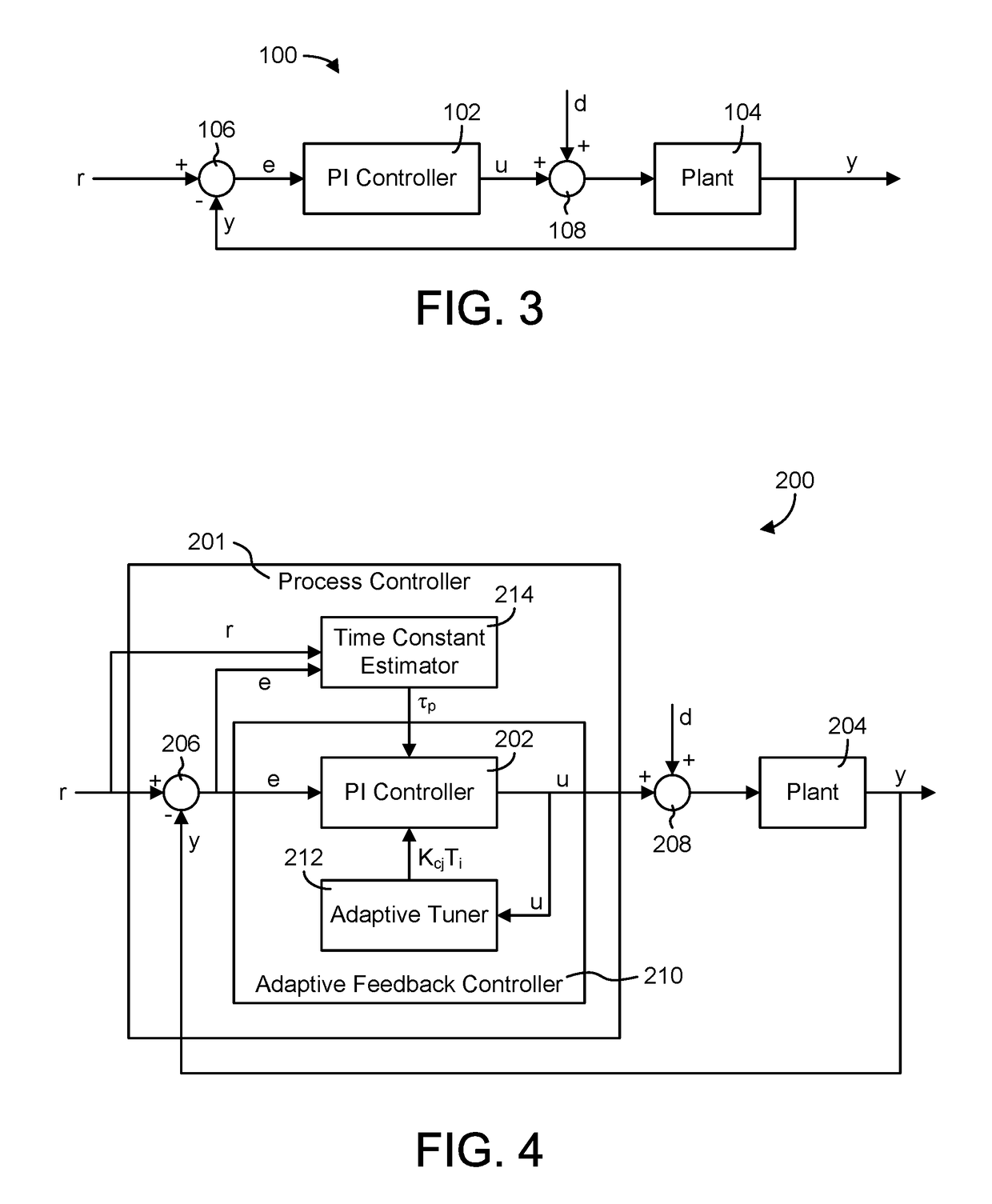
Feedback control system with normalized performance indices for setpoint alarming
a technology of performance indices and control systems, applied in the field of calculating performance indices for feedback controllers, can solve the problems of inability to directly compare performance measures across systems or controllers, inability to use such methods, and high computational costs of traditional methods for calculating normalized index values
- Summary
- Abstract
- Description
- Claims
- Application Information
AI Technical Summary
Benefits of technology
Problems solved by technology
Method used
Image

Examples
example 1
op First-Order System
[0111]For this example, assume that the specified time constant is τs and the actual time constant of the closed-loop system is τa. Let the AR(1) parameter for the actual closed-loop system be defined as:
[0112]b=e-Δtτa
The AR(1) representation of the error signal in the actual closed-loop system is then:
ek=bek−1+dk
[0113]The AR(1) parameter derived from the specified time constant is:
[0114]a=e-Δtτs
[0115]The first estimate of the variance (i.e., ν1) can be calculated from the following:
ν1=σe2(1−α2)
and the second estimate of the variance (i.e., ν2) is derived in the following steps:
{circumflex over (d)}k=ek−αek−1
ν2=var({circumflex over (d)}k)=E[(ek=αek−1)2]
ν2=E[ek2−αekek−1+α2ek−12]
ν2σe2(1+α2)−2ασe2ρ1
where ρ1 is the lag-one autocorrelation of e, which for the AR(1) process is defined as:
ρ1=b
The expression for ν2 can be simplified to:
ν2=σe2(1+α2−2αb)
[0116]The ratio of the two variance estimates is:
[0117]I2=σe2(1-2ab+a2)σe2(1-a2)I2=1-2ab+a21-a2
[0118]Substit...
example 2
l Signal Due to Loop Oscillations
[0123]For an oscillating loop, the error signal can be expressed as:
e(t)=K sin(2πft)
The variance of this error signal is:
[0124]σe2=K22
and the second estimate of the variance can be written as:
e(t)−αe(t−Δt)=K sin(2πft)−αK sin(2πf(t−Δt))
[0125]The preceding equation can be simplified by applying trigonometric identities to give:
[0126]e(t)-ae(t-Δt)=Ksin(2πft)-aKcos(2πfΔt)sin(2πft)+aKsin(2πfΔt)cos(2πft)=K[(1-acos(2πfΔt))sin(2πft)+asin(2πfΔt)cos(2πft)]=K[Asin(2πft)+Bcos(2πft)]=KA2+B2sin(2πf(t+φ))
[0127]The second estimate of the variance ν2 is therefore given by:
[0128]v2=K2(A2+B2)2v2=K2(a2-2cos(2πfΔt)a+1)2
and the ratio of the two variances is:
[0129]I2=v2v1=a2-2cos(2πfΔt)a+11-a2
[0130]The preceding equation shows that I2 is a periodic function of frequency f. As frequency f approaches zero, the value of I2 is:
[0131]I2(f→0)...
PUM
 Abstract
Description
Claims
Application Information