Dual screen treatment system

a treatment system and dual screen technology, applied in the nature of treatment water, sedimentation settling tanks, separation processes, etc., can solve the problems of fines, slow filtration rate to an ineffective flow rate, and limited reactivity of media surfaces, etc., to achieve the effect of easy and inexpensiv

Inactive Publication Date: 2019-02-12
OLDCASTLE INFRASTRUCTURE INC
View PDF56 Cites 20 Cited by
  • Summary
  • Abstract
  • Description
  • Claims
  • Application Information

AI Technical Summary

Benefits of technology

[0017]An objective of the present invention is to provide vaults, boxes, systems, and methods of using treatment systems to capture pollutants from storm water runoff and prevent the conveyance of these pollutants from entering a receiving water body or landscape area, which is designed to be a part of a local permanent storm water drainage infrastructure, where the system combines both drainage conveyance, multi-level treatment techniques, variable hydraulic capabilities, and easy and inexpensive methods for servicing the invention.

Problems solved by technology

The result of exceeding these numeric values will result with the state of Florida being fined by the EPA.
A difficulty with physical filtration is that the collected solids can become so numerous that the rate of filtration is slowed to an ineffective flow rate.
However, the reactivity of the media surfaces is limited by the number of receptors on the surface of the media.
However, the smaller the granular size of the media the more likely the media will be to bind due to the collection of solids within the media.

Method used


Image

  • Dual screen treatment system
  • Dual screen treatment system
  • Dual screen treatment system

Examples


first embodiment

Dual Vortex Baffle Box / Vault / System

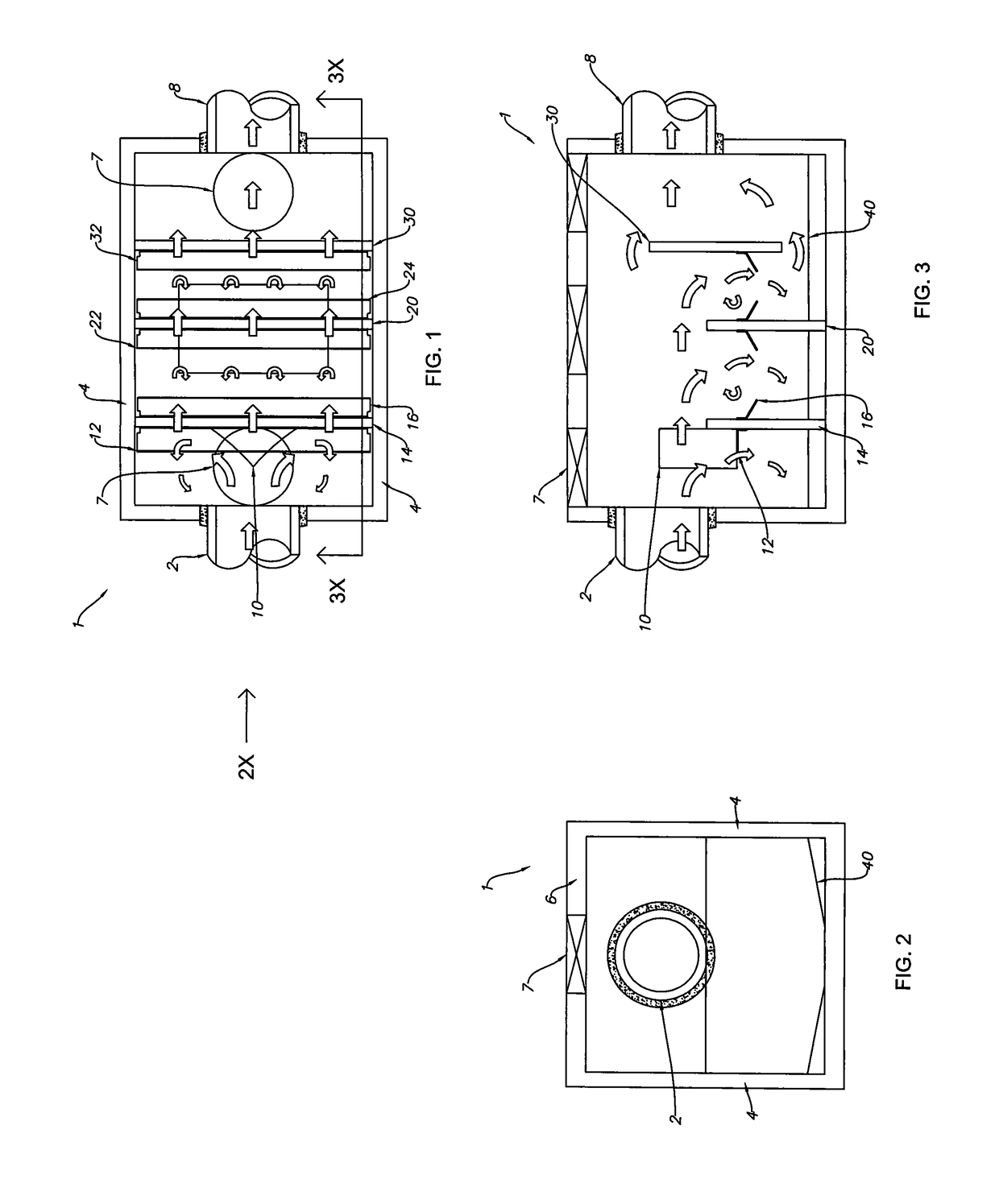
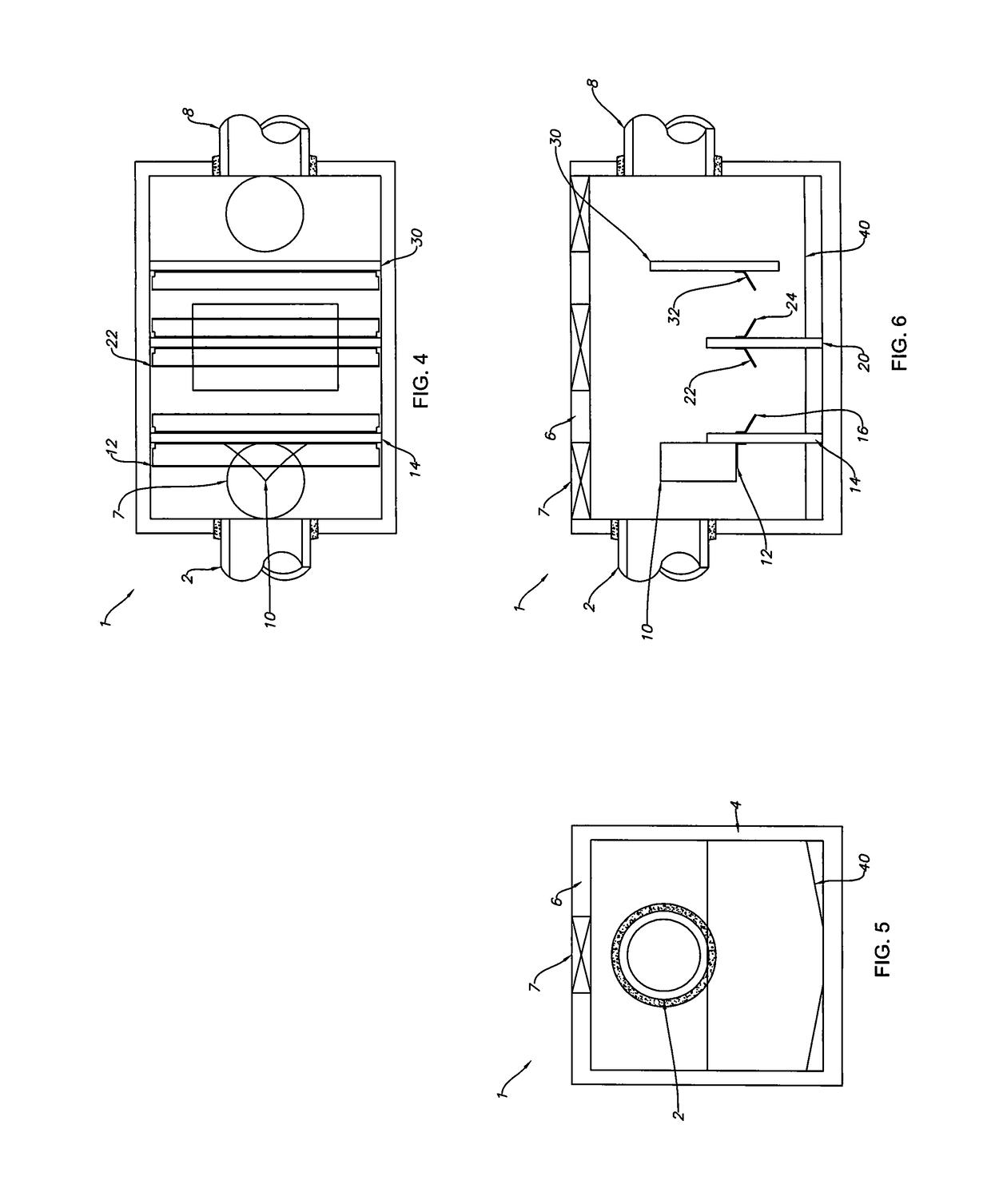
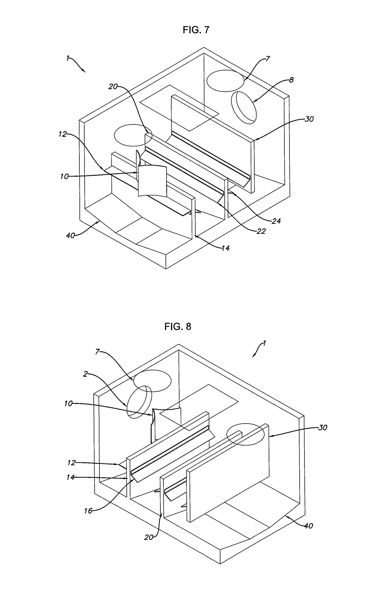
[0120]FIG. 1 is a top view of a dual vortex baffle box 1 with 40 sloped floors, flow spreader 10, shelf 12, baffles 14, 20, 30 and baffle deflectors 16, 22, 24, 32 and arrows showing water flow. FIG. 2 is an inflow end view of the dual vortex baffle box 1 of FIG. 1 along arrow 2X. FIG. 3 is a side cross-sectional view of the dual vortex baffle box 1 of FIG. 1 arrows 3X. FIG. 4 is another top view of the dual vortex baffle box 1 of FIG. 1 without arrows. FIG. 5 is another inflow end view of the dual vortex baffle box 1 of FIG. 2. FIG. 6 is another side cross-sectional view of the dual vortex baffle box 1 of FIG. 3. FIG. 7 is an upper front right perspective view of the dual vortex baffle box 1 of FIG. 1. FIG. 8 is an upper rear left perspective view of the dual vortex baffle box 1 of FIG. 1. FIG. 9 is an upper rear right perspective view of the dual vortex baffle box 1 of FIG. 1. FIG. 10 is an upper front left perspective view of the dual vortex baf...

second embodiment

Dual Baffle Box / Vault System with Screen Systems and Hinging Lids

[0131]FIG. 11 is a top view of the dual screen baffle box 50 with first (left side) screen box 60 and second (right side) screen box 70 and arrows showing water flow. FIG. 12 is an inflow end view of the dual screen baffle box 50 of FIG. 11 along arrow 12X. FIG. 13 is a side cross sectional view of the dual screen baffle box 50 of FIG. 11 along arrows 13X. FIG. 14 is another top view of the dual screen baffle box 50 of FIG. 11 without arrows. FIG. 15 is another inflow end view of the dual screen baffle box 50 of FIG. 12. FIG. 16 is another side cross-sectional view of the dual screen baffle box 50 of FIG. 13. FIG. 17 is an upper front right perspective view of the baffle box 50 of FIG. 11. FIG. 18 is an upper rear left perspective view of the baffle box 50 of FIG. 11. FIG. 19 is an upper rear right perspective view of the baffle box 50 of FIG. 11. FIG. 20 is an upper front left perspective view of the baffle box 50 of ...

third embodiment

Dual Baffle Box / Vault / System with Screened Systems and Screened Media Vessel

[0136]FIG. 21 is a top view of the dual screen baffle box 80 with screened media vessel 90 and arrows showing water flow. FIG. 22 is an inflow end view of the dual screen baffle box 80 of FIG. 21 along arrow 22X. FIG. 23 is a side cross sectional view of the dual screen baffle box 80 of FIG. 21 along arrows 23X. FIG. 24 is another top view of the dual screen baffle box 80 of FIG. 21 without arrows. FIG. 25 is another inflow end view of the dual screen baffle box 80 of FIG. 22. FIG. 26 is another side cross-sectional view of the dual screen baffle box 80 of FIG. 23. FIG. 27 is an upper front right perspective view of the baffle box 80 of FIG. 21. FIG. 28 is an upper rear left perspective view of the baffle box 80 of FIG. 21. FIG. 29 is an upper rear right perspective view of the baffle box 80 of FIG. 21. FIG. 30 is an upper front left perspective view of the baffle box 80 of FIG. 21.

[0137]Referring to FIGS. 2...


PUM

PropertyMeasurementUnit
diametersaaaaaaaaaa
invert elevationaaaaaaaaaa
pressureaaaaaaaaaa

Abstract

Vaults, boxes, systems, and methods of treatment systems to capture pollutants from storm water runoff and prevent the conveyance of these pollutants from entering a receiving water body or landscape area, which is designed to be a part of a local permanent storm water drainage infrastructure. A single treatment box, vault and system combines both drainage conveyance, multi-level treatment techniques, variable hydraulic capabilities, and easy and inexpensive methods for servicing the system. A flow spreader can split incoming water to pass into dual screen filtration systems. The system can include components selected from a shelf beneath the spreader, at least one baffle, skimmer, deflectors, media filtration and water pressure lines with spray heads for cleaning debris on a sloped floor.

Description

CROSS REFERENCE TO RELATED APPLICATIONS[0001]This application is a Continuation-In-Part of U.S. patent application Ser. No. 14 / 288,455 filed May 28, 2014, now abandoned, which claims the benefit of priority to U.S. Provisional Patent Application Ser. No. 61 / 828,958 filed May 30, 2013. The entire disclosure of each of the applications listed in this paragraph are incorporated herein by specific reference thereto.FIELD OF INVENTION[0002]This invention relates to water detention and treatment, and in particular to vaults, boxes, systems, and methods of treatment systems to capture pollutants from storm water runoff and prevent the conveyance of these pollutants from entering a receiving water body or landscape area, which is designed to be a part of a local permanent storm water drainage infrastructure, where a single treatment system combines both drainage conveyance, multi-level treatment techniques, variable hydraulic capabilities, and easy and inexpensive methods for servicing the ...

Claims


Application Information

Patent Timeline
Patent Type & Authority Patents(United States)
IPC IPC(8): E03F5/14B01D21/24B01D24/02C02F1/00E03F5/04B01D21/00E03F5/00C02F103/00
CPCC02F1/004E03F5/14B01D24/02B01D21/2472E03F5/0403E03F5/0404B01D21/0012B01D21/0087E03F5/00C02F2103/001C02F2303/24C02F1/00B01D24/04B01D21/0003B01D21/0006B01D21/003B01D21/0033B01D2221/12C02F1/001
Inventor HAPPEL, TOM
Owner OLDCASTLE INFRASTRUCTURE INC
Why Eureka
Try Eureka