Voltage application device and discharge device

a discharge device and application device technology, applied in the direction of corona discharge, atomized substances, disinfection, etc., can solve the problems of increasing the amount of unnecessary ozone generated and so as to suppress increase the amount of radicals produced, and suppress the effect of the increase in the amount of ozone generated

Active Publication Date: 2019-02-19
PANASONIC INTELLECTUAL PROPERTY MANAGEMENT CO LTD
View PDF9 Cites 0 Cited by
  • Summary
  • Abstract
  • Description
  • Claims
  • Application Information

AI Technical Summary

Benefits of technology

[0004]In this kind of discharge device, the voltage application circuit applies a voltage to the discharge electrode, thereby generating corona discharge. Liquid is supplied to the discharge electrode, and then electrostatic atomization is achieved during the discharge, thereby producing charged fine particulate liquid including radicals as an active ingredient. The charged fine particulate liquid including the radicals exerts advantageous effects such as sterile filtration and odor elimination.
[0005]Incidentally, in the discharge device, introduced energy is preferably increased to increase an amount of radicals produced that eventually exerts various advantageous effects. However, in the above-described conventional discharge device, when the introduced energy is merely increased, the amount of radicals produced is increased, but an amount of unnecessary ozone generated may also be increased.SUMMARY
[0006]The present disclosure is made in consideration of such a circumstance, and an object of the present disclosure is to provide a voltage application device and a discharge device capable of suppressing increase in an amount of ozone generated, while increasing an amount of radicals produced.
[0007]A voltage application device of a first aspect includes a voltage application circuit and a control circuit. The voltage application circuit is configured to apply a voltage to a load including a discharge electrode to cause the discharge electrode to discharge. The control circuit is configured to control the voltage application circuit based on a monitoring target including at least one of an output current and an output voltage of the voltage application circuit. The control circuit causes the voltage application circuit to alternately repeat a first mode and a second mode. The first mode is a mode that raises the voltage while time elapses, and generates a discharge current by promoting corona discharge to dielectric breakdown. The second mode is a mode that lowers the voltage to cut off the discharge current by causing the load to be in an overload state against the voltage application circuit. The control circuit causes the voltage application circuit to operate in the first mode when magnitude of the monitoring target is less than a threshold, and causes the voltage application circuit to operate in the second mode when the magnitude of the monitoring target is not less than the threshold.
[0008]In the first aspect, the voltage application device of a second aspect further includes a time adjuster that adjusts a length of a discharge period, and the dielectric breakdown is periodically generated at the discharge period.
[0009]In the second aspect, the voltage application device of a third aspect includes an isolation transformer, and is configured to boost an input voltage that is input to a primary side of the isolation transformer, and to apply the voltage to the load that is electrically connected to a secondary side of the isolation transformer. The time adjuster is disposed on the primary side of the isolation transformer.

Problems solved by technology

However, in the above-described conventional discharge device, when the introduced energy is merely increased, the amount of radicals produced is increased, but an amount of unnecessary ozone generated may also be increased.

Method used


Image

  • Voltage application device and discharge device
  • Voltage application device and discharge device
  • Voltage application device and discharge device

Examples


first exemplary embodiment

[0026](1) Outline

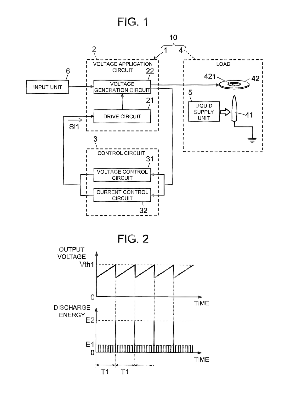
[0027]As illustrated in FIG. 1, voltage application device 1 according to the present exemplary embodiment includes voltage application circuit 2 and control circuit 3. Voltage application device 1 is a device causing discharge electrode 41 to perform a discharge by applying a voltage to load 4 including discharge electrode 41.

[0028]Further, as illustrated in FIG. 1, discharge device 10 according to the present exemplary embodiment includes voltage application device 1, discharge electrode 41, load 4 including opposite electrode 42 disposed so as to face discharge electrode 41, and liquid supply unit 5 that supplies liquid to discharge electrode 41. More specifically, discharge device 10 includes voltage application circuit 2, control circuit 3, liquid supply unit 5, discharge electrode 41, and opposite electrode 42 as components thereof. However, discharge device 10 may include at least voltage application device 1 and discharge electrode 41 as components thereof, ...

second exemplary embodiment

[0091]Voltage application device 1A and discharge device 10A according to the present exemplary embodiment are different from voltage application device 1 and discharge device 10 according to the first exemplary embodiment in that time adjuster 7 is further provided as illustrated in FIG. 5. Hereinafter, constituent elements identical to those of the first exemplary embodiment are denoted by like reference signs and explanations thereof will be omitted.

[0092]Time adjuster 7 is configured to adjust a length of a discharge period. More specifically, in voltage application device 1A according to the present exemplary embodiment, time adjuster 7 can adjust a length of a period of generation of the dielectric breakdown (discharge period) in the leader discharge in which the dielectric breakdown is intermittently generated.

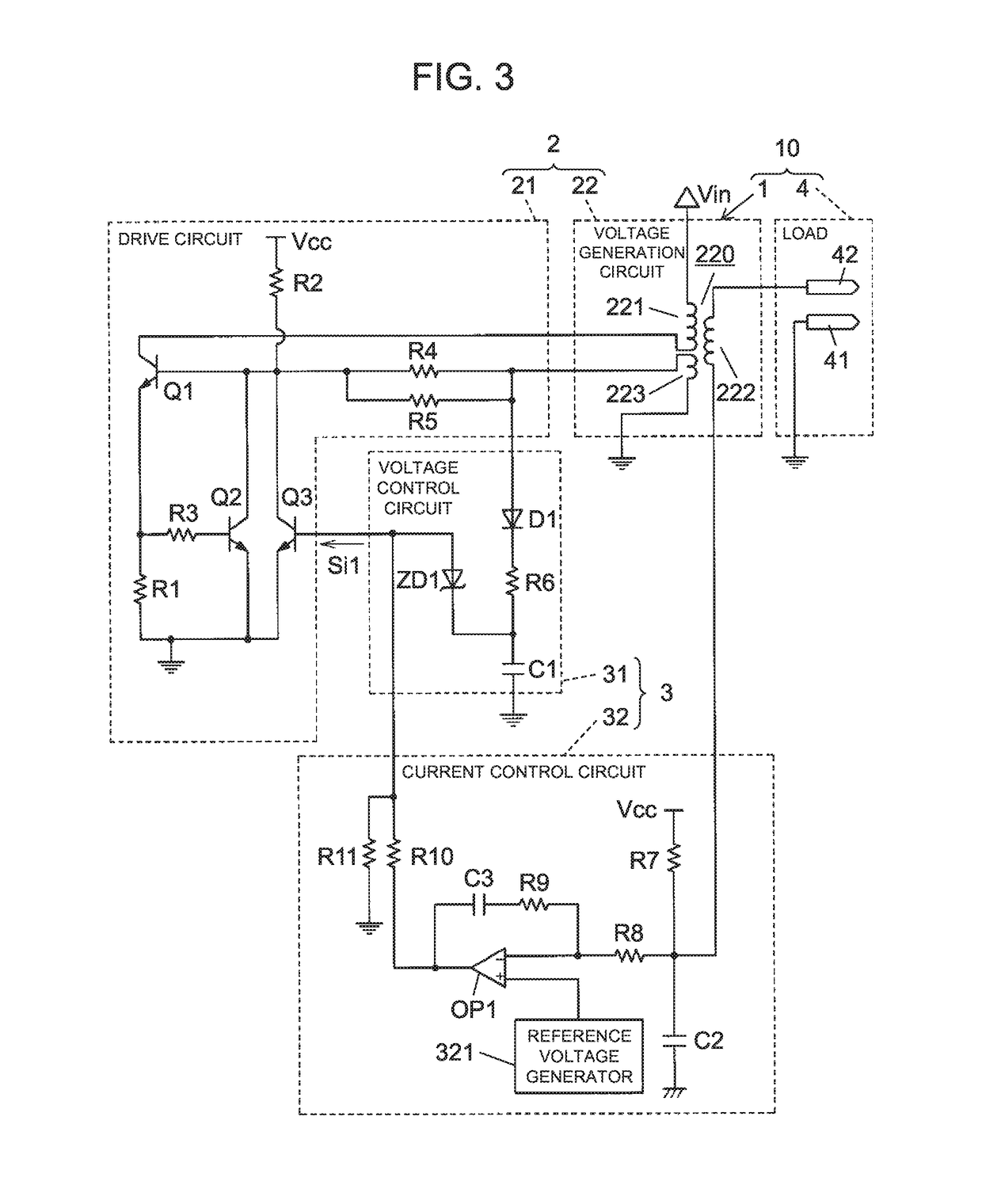
[0093]Incidentally, voltage application circuit 2 includes isolation transformer 220 (refer to FIG. 3). Voltage application circuit 2 is configured to boost input volta...

third exemplary embodiment

[0109]Voltage application device 1B and discharge device 10B according to the present exemplary embodiment are different from voltage application device 1A and discharge device 10A according to the second exemplary embodiment in that time adjuster 7 automatically adjusts the length of the discharge period, as illustrated in FIG. 8. Hereinafter, constituent elements identical to those of the second exemplary embodiment are denoted by like reference signs and explanations thereof will be omitted.

[0110]In the present exemplary embodiment, time adjuster 7 is configured to adjust the length of the discharge period according to an output of sensor 9. Sensor 9 detects a condition around discharge electrode 41. Sensor 9 detects information on environment (condition) around discharge electrode 41, such as a temperature, humidity, an odor index, illuminance, and presence of a person around discharge electrode 41. The present exemplary embodiment will be described such that voltage application...


PUM

PropertyMeasurementUnit
direct-current (DC) voltageaaaaaaaaaa
voltageaaaaaaaaaa
discharge frequencyaaaaaaaaaa

Abstract

A voltage application device according to the present disclosure includes a voltage application circuit and a control circuit. The control circuit causes the voltage application circuit to alternately repeat a first mode and a second mode. The first mode is a mode that raises a voltage while time elapses, and generates a discharge current by promoting corona discharge to dielectric breakdown. The second mode is a mode that lowers the voltage to cut off the discharge current by causing a load to be in an overload state against the voltage application circuit. This can suppress an amount of ozone generated, while increasing an amount of radicals produced.

Description

RELATED APPLICATIONS[0001]This application claims the benefit of Japanese Application No. 2016-175902, filed on Sep. 8, 2016, the entire disclosure of which Application is incorporated by reference herein.BACKGROUND1. Technical Field[0002]The present disclosure generally relates to a voltage application device and discharge device. More specifically, the present disclosure relates to a voltage application device and a discharge device, which apply a voltage to a load including a discharge electrode to generate discharge.2. Description of the Related Art[0003]Unexamined Japanese Patent Publication No. 2011-67738 proposes a discharge device including a discharge electrode and a voltage application circuit (electric power supply unit).[0004]In this kind of discharge device, the voltage application circuit applies a voltage to the discharge electrode, thereby generating corona discharge. Liquid is supplied to the discharge electrode, and then electrostatic atomization is achieved during...

Claims


Application Information

Patent Timeline
Patent Type & Authority Patents(United States)
IPC IPC(8): B01J19/08B05B5/10H01T19/00B05B5/00A61L9/12A61L9/14A61L9/04
CPCB01J19/088A61L9/046A61L9/12A61L9/14B05B5/005H01T19/00B05B5/10B01J2219/0877A61L2209/212A61L2209/213B01J2219/0801B01J2219/0849B05B5/007B05B5/0533
Inventor NAKANO, YUKARISAIDA, ITARU
Owner PANASONIC INTELLECTUAL PROPERTY MANAGEMENT CO LTD
Why Eureka
Try Eureka