
Wind turbine with thermal battery using noncombustible fuels for storing regenerating energy

Inactive Publication Date: 2019-02-19
ANTHONY MICHAEL MARK
View PDF5 Cites 1 Cited by
  • Summary
  • Abstract
  • Description
  • Claims
  • Application Information

AI Technical Summary

Benefits of technology

This patent describes a vertical wind turbine that is designed to collect and convert wind energy into electrical power. The turbine is made up of various components including a horizontal turbine casing, a vertical casing, and a vertical shaft. The horizontal turbine casing is attached to the vertical casing and rotates to face the wind in a maximum flow position. The vertical shaft is supported by bearings and holds a set of turbine blades that are connected to it. The horizontal shaft has a solar lens atop it that is aligned with the axis of the vertical shaft. The solar lens is attached to a thermal battery using bolts and the vertical casing is connected to a vacuum case. The vacuum case is designed to reduce heat loss and the internal walls of the vertical casing are highly reflective to prevent heat loss. The vertical shaft has slits for the intake and exhaust ports to minimize pressure drop and the exhaust lines are connected to a radiator for heating or cooling the fluid. The invention aims to provide an efficient and reliable wind turbine that is easy to operate and maintain.

Problems solved by technology

The rotation of such turbines is generally uncontrolled since it depends on the variable motion of wind.

Method used


Image

  • Wind turbine with thermal battery using noncombustible fuels for storing regenerating energy
  • Wind turbine with thermal battery using noncombustible fuels for storing regenerating energy
  • Wind turbine with thermal battery using noncombustible fuels for storing regenerating energy

Examples


first preferred embodiment

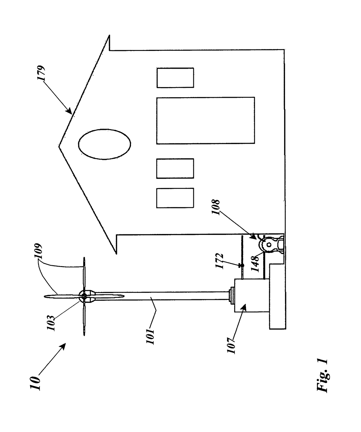
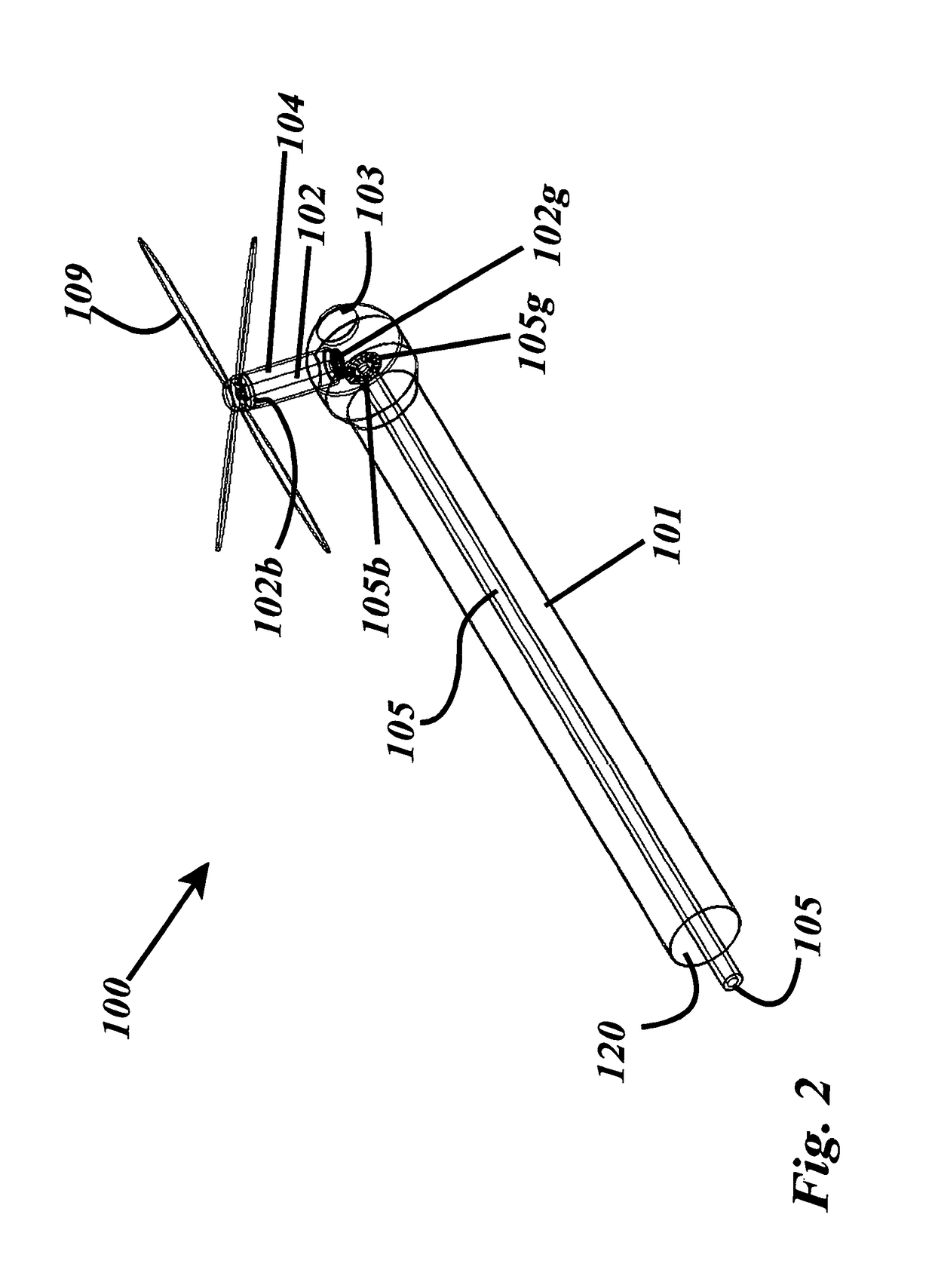
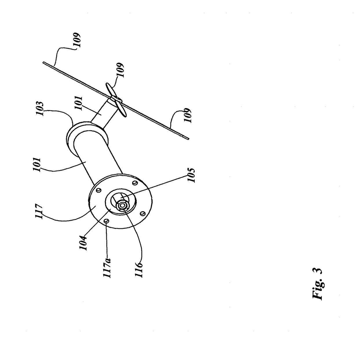
[0086]The present invention accomplishes the above-stated objectives, as well as others, as may be determined by a fair reading and interpretation of the entire specification. The present invention relates generally to the field of thermal engine and thermal batteries for storage and regeneration of wind energy using wind turbines.

[0087]Referring to FIGS. 1-18, a thermal engine assembly is disclosed, a preferred embodiment of which takes the form of a wind turbine assembly 100. More specifically, the present wind turbine assembly 100 charges a thermal battery 107 for powering a thermal engine 108, to in turn power water pumps, refrigerators, and for heating and cooling.

[0088]In a first embodiment of the invention, the apparatus includes a thermal battery 107 for storing heat including a thermal mass 119 within a thermal battery 107 vacuum case 118 and a means of charging the thermal battery 107 using wind energy and solar energy. A means of charging the thermal battery 107 with ther...


PUM


Abstract

A thermal engine includes a thermal battery with a thermal mass for storing regenerative wind and solar energy using a solar lens and mechanical friction generated by the rotation of a wind turbine. The thermal engine comprises a thermal battery; a thermal engine; means of charging the thermal battery using natural energy including a solar lens; a wind turbine; and charging by electrical means. The invention further comprises a means of converting stored thermal energy to mechanical power using non-combustible fluids to drive devices such as an electric generator, a water pump; a means of using said thermal energy to directly heat homes and industrial facilities; a means of using said thermal energy for cooling homes and industrial facilities.

Description

FILING HISTORY[0001]This Application is a continuation-in-part of application Ser. No. 14 / 545,996, filed on Jul. 15, 2015, which is a continuation-in-part of application Ser. No. 13 / 506,943, filed on May 25, 2012, issuing into U.S. Pat. No. 9,500,158, which is continuation-in-part of application Ser. No. 13 / 506,943 filed on May 25, 2012, which is a continuation-in-part of application Ser. No. 12 / 380,626, filed on Mar. 2, 2009, issuing into U.S. Pat. No. 8,186,160 on May 29, 2012.BACKGROUND OF THE INVENTION1. Field of the Invention[0002]The present invention relates generally to the field of thermal batteries and thermal engines using non-combustible fuels for storing thermal energy and reusing this energy at a later time. The field extends to the use of a charging means for such thermal batteries including wind turbines, solar heating, electrical power and other means for storing reusable thermal energy for later regeneration. More specifically the present invention relates to a the...

Claims


Application Information

Patent Timeline
IPC IPC(8): F03G6/06F03D9/18F03B3/00F24S23/30F24S20/40F28D20/02
CPCF03B3/00F03G6/06F03D9/18F28D20/02F24S20/40F24S23/30Y02B10/30Y02E10/74F05B2220/70F01B29/06F02B5/00F01K21/02F02B53/02F01K3/18F01K27/02F22B3/06F03D9/22F24S80/56F24S80/54F24S60/10F24S10/70Y02E10/44Y02E10/46Y02E10/72Y02P90/50Y02B10/20Y02E60/36Y02P80/10Y02P80/20Y02T10/12Y02E70/30F03G6/068C25B1/04
Inventor ANTHONY, MICHAEL MARK
Owner ANTHONY MICHAEL MARK
Learn More