Weapon fire detection and localization system for electro-optical sensors

a technology of electro-optical sensors and fire detection, applied in the field of detection systems, can solve the problems of clutter sources, complex detection methodologies, and -optical weapons fire detections often involve severely reduced signature intensities, and achieve the effect of minimizing false detections and high detection rates

Active Publication Date: 2019-02-19
UNITED STATES OF AMERICA THE AS REPRESENTED BY THE SEC OF THE ARMY
View PDF10 Cites 0 Cited by
  • Summary
  • Abstract
  • Description
  • Claims
  • Application Information

AI Technical Summary

Benefits of technology

[0005]A detection system that operates on the output of an imaging detection sensor system based on three electro-optical imagers is presented here. The detection method is able to extract weapons fire signatures of high signal intensity in the near field, as well as very low intensity weapons fire signatures in the far field, with a high detection rate. The detection method minimizes false detections from clutter sources. The detection method discriminates weapons fire signatures from background by analyzing characteristics of the extracted signature. Features of the extracted signature are used to classify the detection as either weapons fire or false alarm, where weapon fire can be subdivided into anti-tank guided missile (ATGM), recoilless rifle (RR), and rocket propelled grenade (RPG). Weapon fire is not limited to ATGM, RR, and RPG, but can include other sources such as small arms fire, and main gun fire from tanks and armored fighting vehicles, as the system is intended to detect a blast, including muzzle flash, created by the launch of a projectile from a gun barrel, rocket tube or similar device.

Problems solved by technology

Electro-optical weapons fire detection systems for ground application, capable of detecting short and long range threats require complex detection methodologies to accurately detect weapons fire over a broad dynamic range of signal intensity.
Long range electro-optical weapons fire detections often involve severely reduced signature intensities due to atmospheric degradation.
Additionally, near field motion can generate clutter sources of similar intensities to far field weapons fire.

Method used


Image

  • Weapon fire detection and localization system for electro-optical sensors
  • Weapon fire detection and localization system for electro-optical sensors
  • Weapon fire detection and localization system for electro-optical sensors

Examples


Embodiment Construction

[0016]The First Exemplary Weapon Fire Detection and Localization System.

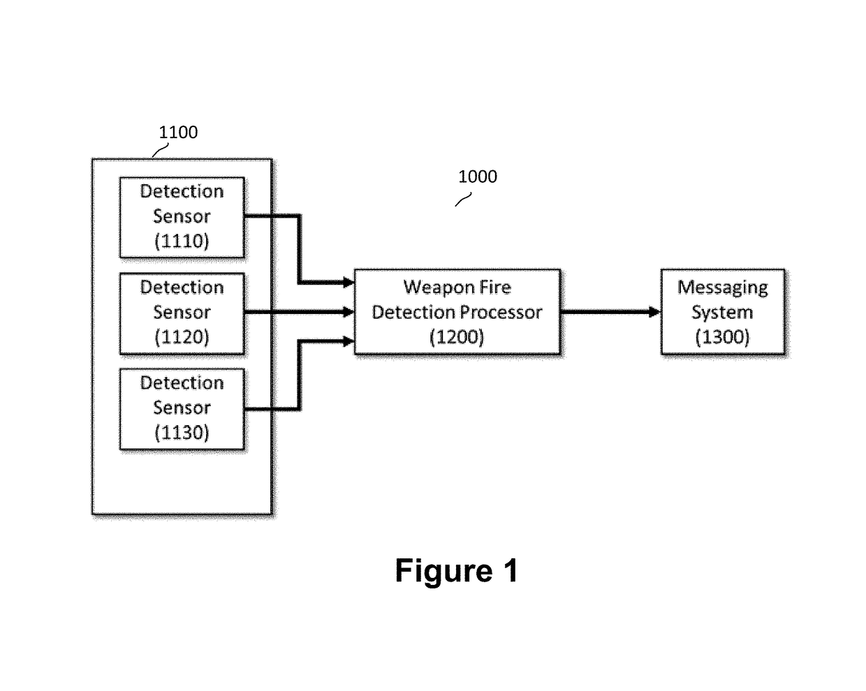
[0017]FIG. 1 describes the first exemplary weapon fire detection and localization system. The system (1000) is comprised of a weapon fire detection imaging sensor system (1100), a processor (1200), and a messaging system (1300). The weapon fire detection imaging sensor system is comprised of three imaging detection sensors (1110, 1120, 1130), each of which images in a different spectral range. The video output of the detection sensor is provided as an input to the processor. The processor hosts the weapon fire detection and localization algorithm. The messaging system distributes the output results of the weapon fire detection and localization algorithm to other connected systems, providing an alert message.

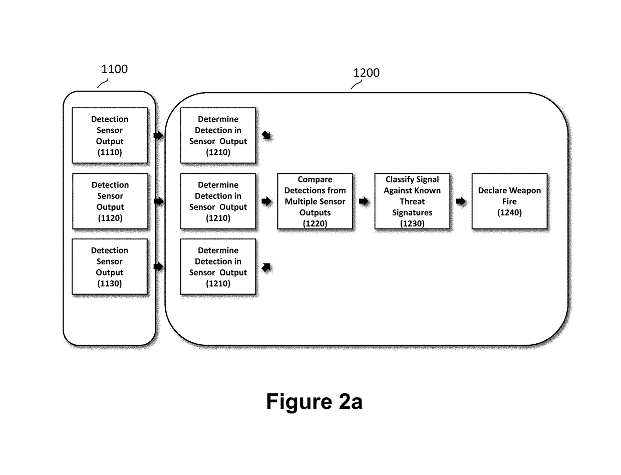
[0018]FIG. 2a describes the first exemplary weapon fire detection and localization algorithm. For each imaging detection sensor (1110, 1120, 1130), the video output is provided to the processor. Weapon fire d...


PUM


Abstract

An electro-optical imaging sensors system is disclosed for detecting and locating a blast, including muzzle flash, created by the launch of a projectile from a gun barrel, rocket tube or similar device, generally associated with weapons fire. The system is used in conjunction with detection algorithms and provides the azimuth and elevation from the detecting sensor to the location of the blast (the launch location) and also provides the weapon classification.

Description

GOVERNMENT INTEREST[0001]The invention described herein may be manufactured, used, sold, imported, and / or licensed by or for the Government of the United States of America.FIELD OF THE INVENTION[0002]This invention relates to the field of detection systems, and in particular, a system for detecting and locating a blast, including muzzle flash, created by the launch of a projectile from a gun barrel, rocket tube or similar device, generally associated with weapons fire.BACKGROUND OF THE INVENTION[0003]Weapon fire detection and localization can be accomplished using a variety of sensing modalities. Typical modalities include radar, acoustic, electro-optic, or some combination of these. Electro-optical solutions typically exploit projectile launch blast, thermal radiation of in-flight round, and the thermal radiation of rocket motors of missiles and rockets. Electro-optical solutions are often employed for close range small arms, and guided and unguided projectile detection. Additional...

Claims


Application Information

Patent Timeline
Patent Type & Authority Patents(United States)
IPC IPC(8): G01S5/16G01S5/18G01J5/00
CPCG01S5/16G01S5/18G01J5/0014G01J2005/0077G01J3/0264G01J3/28G01J3/2803G01J3/36G01J3/027G01H3/00F41H11/00
Inventor BROWN, JEREMY B.HUTCHISON, III, JOHN E.
Owner UNITED STATES OF AMERICA THE AS REPRESENTED BY THE SEC OF THE ARMY
Why Eureka
Try Eureka