Atomic force microscope with optical guiding mechanism

a technology of optical guiding mechanism and microscope, which is applied in the direction of scanning probe microscopy, measuring devices, instruments, etc., can solve the problems of large mass moving with the scanner, limiting the scanning of eligible samples, and difficult or impossible scanning of moving samples such as some biological samples in liquids, etc., to achieve the effect of improving control system, speeding up speed, and increasing precision

Active Publication Date: 2020-02-18
NANOSURF
View PDF9 Cites 0 Cited by
  • Summary
  • Abstract
  • Description
  • Claims
  • Application Information

AI Technical Summary

Benefits of technology

[0010]While the use of AFMs enabled substantial advances in various fields ranging from semiconductor nanotechnology to biotechnological applications, the requirements on commercial AFMs have increased continuously, in particular with respect to increased speed and increased precision. These requirements are typically addressed with developing on hardware such as for example improved positioners, cantilevers and tips, detectors or on improving the control systems. In this context, approaches to minimize the detection of false deflections play an important role for increasing the performance of AFMs.
[0011]It is therefore an object of the invention to provide an atomic force microscope with an optical guiding mechanism, an optical guiding mechanism for an atomic force microscope, and a method for operating an atomic force microscope with an optical guiding mechanism, which at least partially improve the prior art and avoid at least part of the mentioned disadvantages of the prior art.

Problems solved by technology

However, due to the size and mass of the sample affecting the performance of the piezoelectric scanner, the “sample-scanning” configuration puts limits on the eligible samples for scanning.
In addition, scanning moving samples, such as some biological samples in liquids, is difficult or impossible using the “sample-scanning” configuration.
First approaches to keep the beam on a spot on the cantilever relied on using simply a large cantilever or to mount the complete optical system including the laser source and the PSD on the scanner moving with the probe which, however, leads to a large mass to move with the scanner, thus limiting the performance.

Method used


Image

  • Atomic force microscope with optical guiding mechanism
  • Atomic force microscope with optical guiding mechanism
  • Atomic force microscope with optical guiding mechanism

Examples


Embodiment Construction

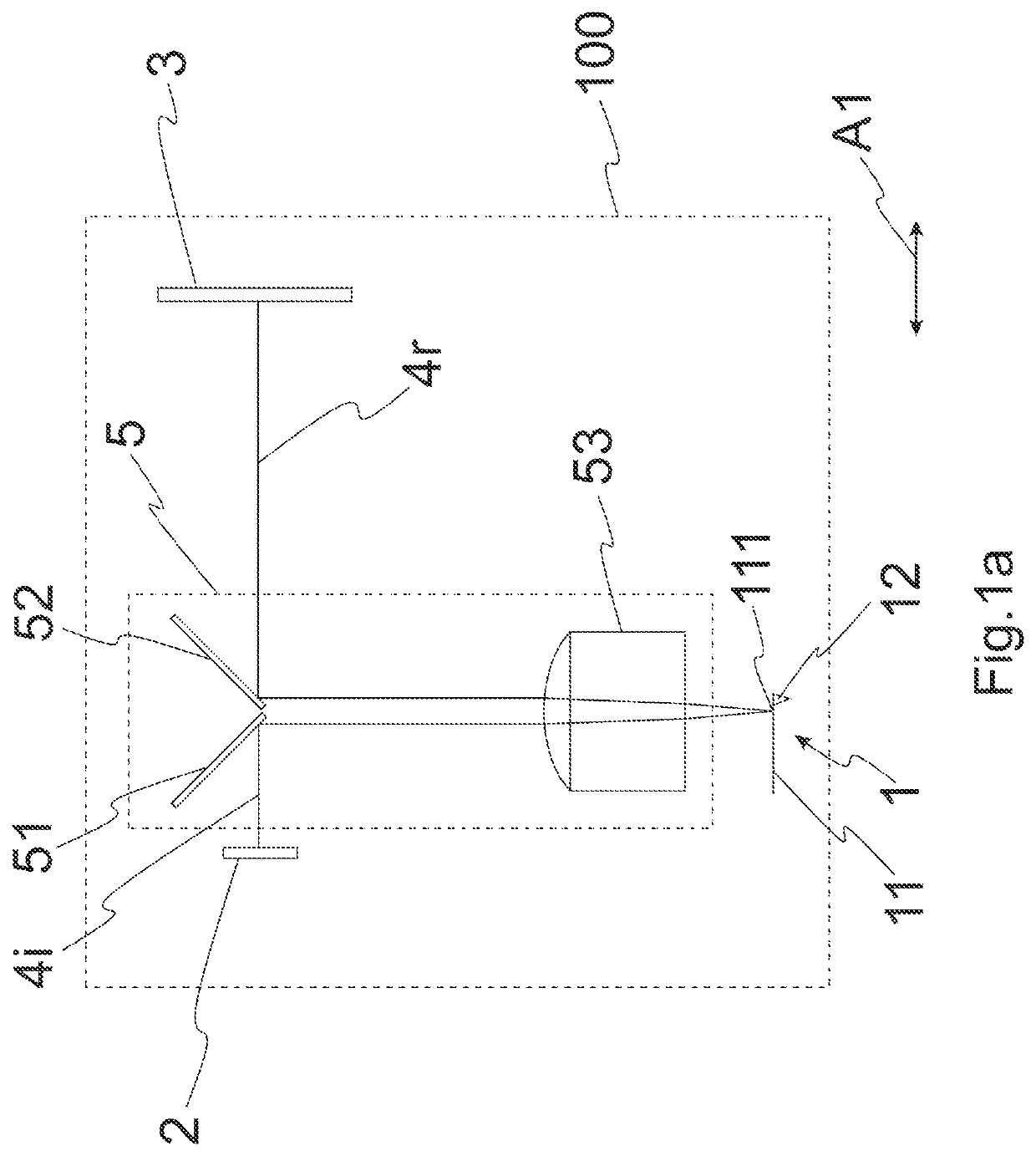
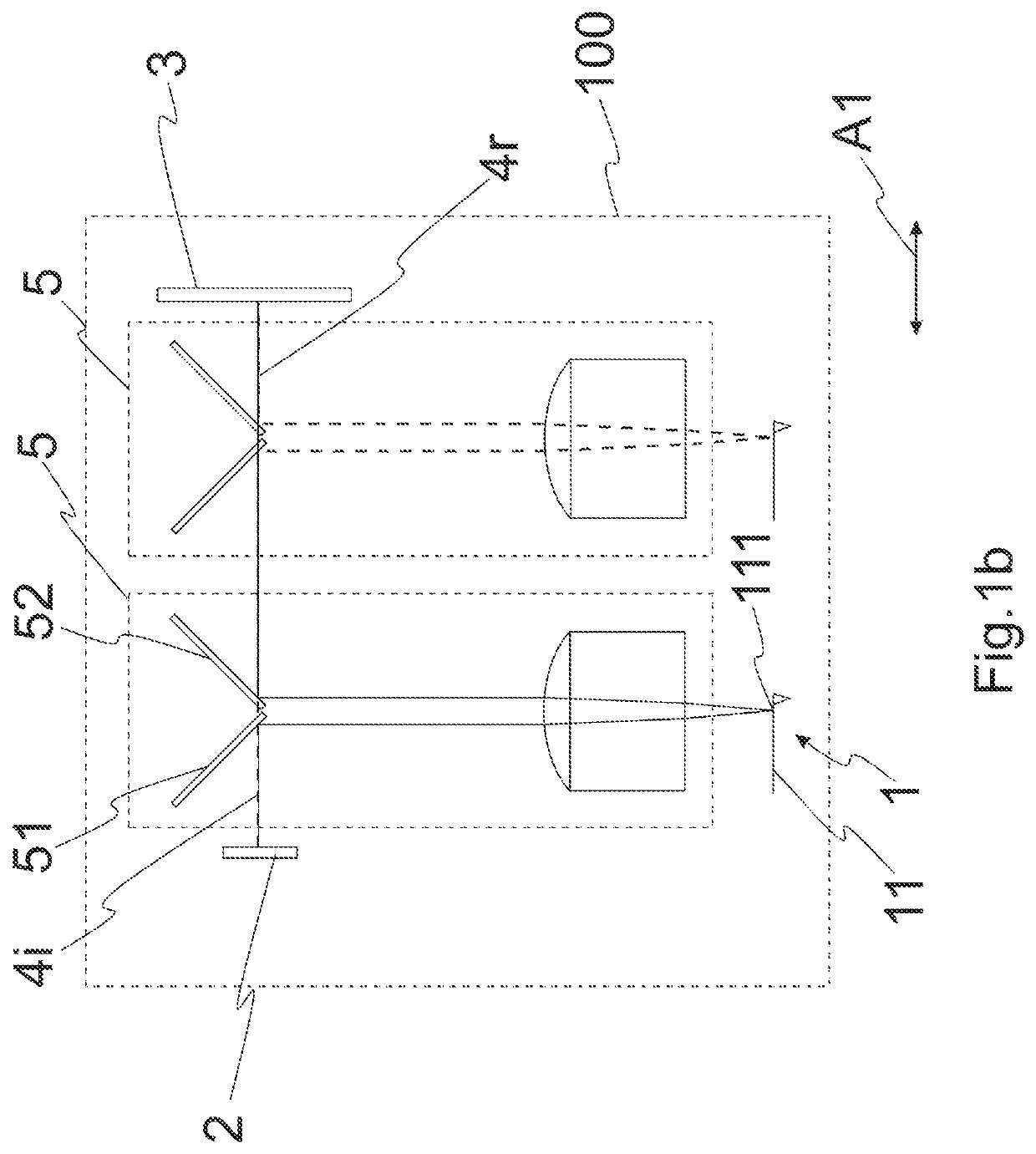
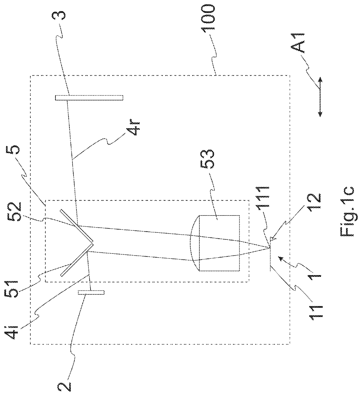
[0061]FIG. 1a shows a simplified block diagram of an embodiment of an AFM 100 comprising a probe a with a cantilever 11 and a tip 12. The probe 1 is attached to a scanner (not shown in the diagram) for scanning the probe 1 along the translational axis A1. The probe 1 is shown for simplicity in a horizontal orientation. Appropriate focusing and / or redirecting optics can be used for directing the laser beam onto a desired position on an inclined probe. FIGS. 1a-e show the simplest example of scanning motion compensation along one translational axis A1. The principle shown in FIGS. 1a-e can accordingly be applied to further translational axes. The AFM 100 further comprises a stationary laser source 2 and a stationary PSD 3 which are arranged on opposite sides of the scanner and on opposite sides of an optical guiding mechanism 5. An incident laser beam 4i is generated by the stationary laser source 2 and guided to the probe 1, where the laser beam 4i impinges on a spot 111 of the canti...


PUM


Abstract

An atomic force microscope includes a scanner for scanning a probe along at least one translational axis, a stationary light source for generating an incident light beam, a stationary position sensitive detector for detecting a light beam reflected from a cantilever, an optical guiding mechanism for compensating a scanning motion of the probe and configured to guide the incident light beam to a spot on the cantilever and to guide the reflected light beam from the cantilever to the position sensitive detector, wherein the optical guiding mechanism includes at least two optical deflection elements per translational axis arranged to move synchronously with the probe along the respective translational axis, and configured to define an optical path between the light source and the detector for the incident and reflected light beam such that the optical path length is independent of the translation of the probe along the respective translational axis.

Description

CROSS-REFERENCE TO RELATED APPLICATION[0001]This application claims priority to Swiss Patent Application No. 01094 / 17 filed Aug. 31, 2017, the disclosure of which is hereby incorporated by reference in its entirety.BACKGROUND OF THE INVENTIONField of the Invention[0002]The present invention relates to an atomic force microscope with an optical guiding mechanism, an optical guiding mechanism for an atomic force microscope, and a method for operating an atomic force microscope with an optical guiding mechanism.RELATED ART[0003]The atomic force microscope (G. Binnig, C. F. Quate and Ch. Gerber, Phys. Rev. Lett. 56, 930, 1986) as a type of a scanning probe microscope (SPM) represents a highly versatile microscopy tool for nanoscale characterization and manipulation. Employing a probe comprising a cantilever with a very sharp tip arranged at a free end of the cantilever, topographic images of a surface with a resolution down to the nanometer or even sub-nanometer range can be achieved. I...

Claims


Application Information

Patent Timeline
Patent Type & Authority Patents(United States)
IPC IPC(8): G01Q20/02G01Q10/00G01Q60/24
CPCG01Q10/00G01Q60/24G01Q20/02
Inventor ADAMS, JONATHAN
Owner NANOSURF
Why Eureka
Try Eureka