Visual display backlight unit

a backlight unit and visual display technology, applied in the field of backlight units, can solve the problems of current backlight designs, problems such as other limitations, and the use of pmma, and achieve the effect of optimizing the length of the iwg and maximising the coupling efficiency

Inactive Publication Date: 2019-02-19
CORNING INC
View PDF30 Cites 0 Cited by
  • Summary
  • Abstract
  • Description
  • Claims
  • Application Information

AI Technical Summary

Benefits of technology

[0007]The present disclosure describes an apparatus comprising coupling a light source into a first intermediate waveguide (IWG) such that the emission area of the light source can be included in the cross section of the IWG. Light is then propagated over the length of the IWG. The LGP is optically coupled to the IWG so that light leaks from the IWG into the LGP over the propagation distance L. Contact between the IWG and the LGP, optionally through an adhesive, as well as the length of the IWG is optimized to obtain maximum coupling efficiency between the IWG and the LGP.

Problems solved by technology

The problem, however, is that the typical size of LED's is, for instance, 1×0.3 millimeters (mm), and coupling light from the LED's into a waveguide with a thickness of about 100 micrometers presents challenges.
Also, for large size panels (e.g. 60 inches, 152.4 centimeters), the use of PMMA is problematic, since PMMA absorbs moisture that can create significant elongation.
Current backlight designs present other limitations.
Also, close to the LED emission points, the optical power density inside the LGP is non-homogeneous, making the first few millimeters of the LGP closest to the LED's to be unusable.

Method used


Image

  • Visual display backlight unit
  • Visual display backlight unit
  • Visual display backlight unit

Examples


Embodiment Construction

[0026]Reference will now be made in detail to embodiments of the present disclosure, examples of which are illustrated in the accompanying drawings. Whenever possible, the same reference numerals will be used throughout the drawings to refer to the same or like parts.

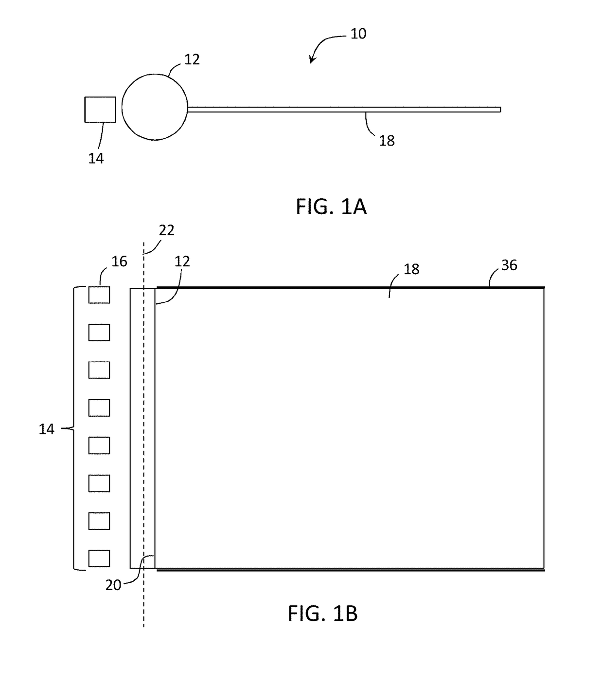
[0027]Backlight units (BLUs) are typically employed as light sources for optical display devices in which the display panel itself does not generate light. This can be illustrated by comparing an organic light emitting diode display panel, wherein the individual organic light emitting diodes each generate light, to a liquid crystal display panel, wherein the liquid crystal material of the display panel only moderates light originating from an outside source. A backlight unit, then, is positioned behind a display panel relative to the viewer position. Light from the backlight unit is passed through the liquid crystal display (LCD) panel, and the liquid crystal material at each pixel position is modified by an electrical ...


PUM


Abstract

A backlight unit suitable for use in illuminating a liquid crystal display panel of a display device. The backlight unit comprises a light guide plate, the light guide plate comprising a glass substrate with at least one edge, an intermediate waveguide physically and optically coupled to the at least one edge along a length of the edge, and a light source optically coupled to the intermediate waveguide.

Description

[0001]This application claims the benefit of priority under 35 U.S.C. § 119 of U.S. Provisional Application No. 61 / 925,857 filed on Jan. 10, 2014, the content of which is relied upon and incorporated herein by reference in its entirety.BACKGROUNDField[0002]The present invention relates generally to a liquid crystal display device, and more particularly to a backlight unit configured to illuminate a display panel of the display device.Technical Background[0003]In liquid crystal displays (LCD's), the backlight unit usually contains a light guide plate (LGP) coupled at the edge thereof to a series of white light emitting diodes (LED's). The LGP is usually made of a plastic material, such as Poly(methyl methacrylate), PMMA, a transparent thermoplastic, with a thickness of about 400 micrometers or more for hand held devices. In some applications, there is a desire to minimize the thickness of the entire LCD stack, and using a thinner LGP presents significant advantages. The problem, howe...

Claims


Application Information

Patent Timeline
Patent Type & Authority Patents(United States)
IPC IPC(8): F21V8/00
CPCG02B6/0028G02B6/003G02B6/0088G02B6/0065G02B6/0045G02B6/0046G02B6/0058G02B6/005
Inventor COMSTOCK, II, LOVELL ELGINDANNOUX, THIERRY LUC ALAINGENG, YINGGOLLIER, JACQUESZHANG, YING
Owner CORNING INC
Why Eureka
Try Eureka