Micro-optics photonic bandgap fiber coupler

Active Publication Date: 2009-12-31
HONEYWELL INT INC
View PDF8 Cites 2 Cited by
  • Summary
  • Abstract
  • Description
  • Claims
  • Application Information

AI Technical Summary

Benefits of technology

[0005]The present invention uses some concepts from existing micro-optics devices such as GRIN or microlens to couple light into and out of fiber. The light from one fiber tip is coupled to a second fiber tip (throughput port) via one GRIN lens having the appropriate pitch such that the maximum coupling efficiency is achieved and having two angled surfaces. The an

Problems solved by technology

Optical components utilizing this cla

Method used


Image

  • Micro-optics photonic bandgap fiber coupler
  • Micro-optics photonic bandgap fiber coupler
  • Micro-optics photonic bandgap fiber coupler

Examples


Embodiment Construction

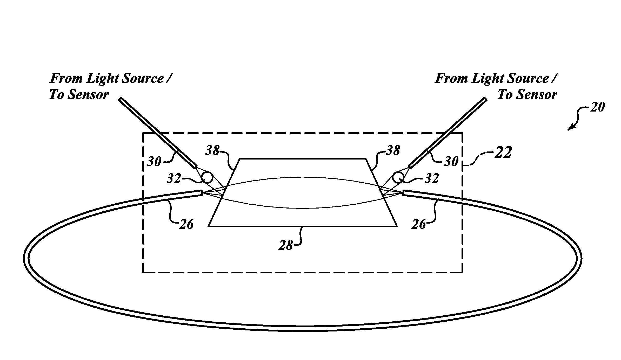
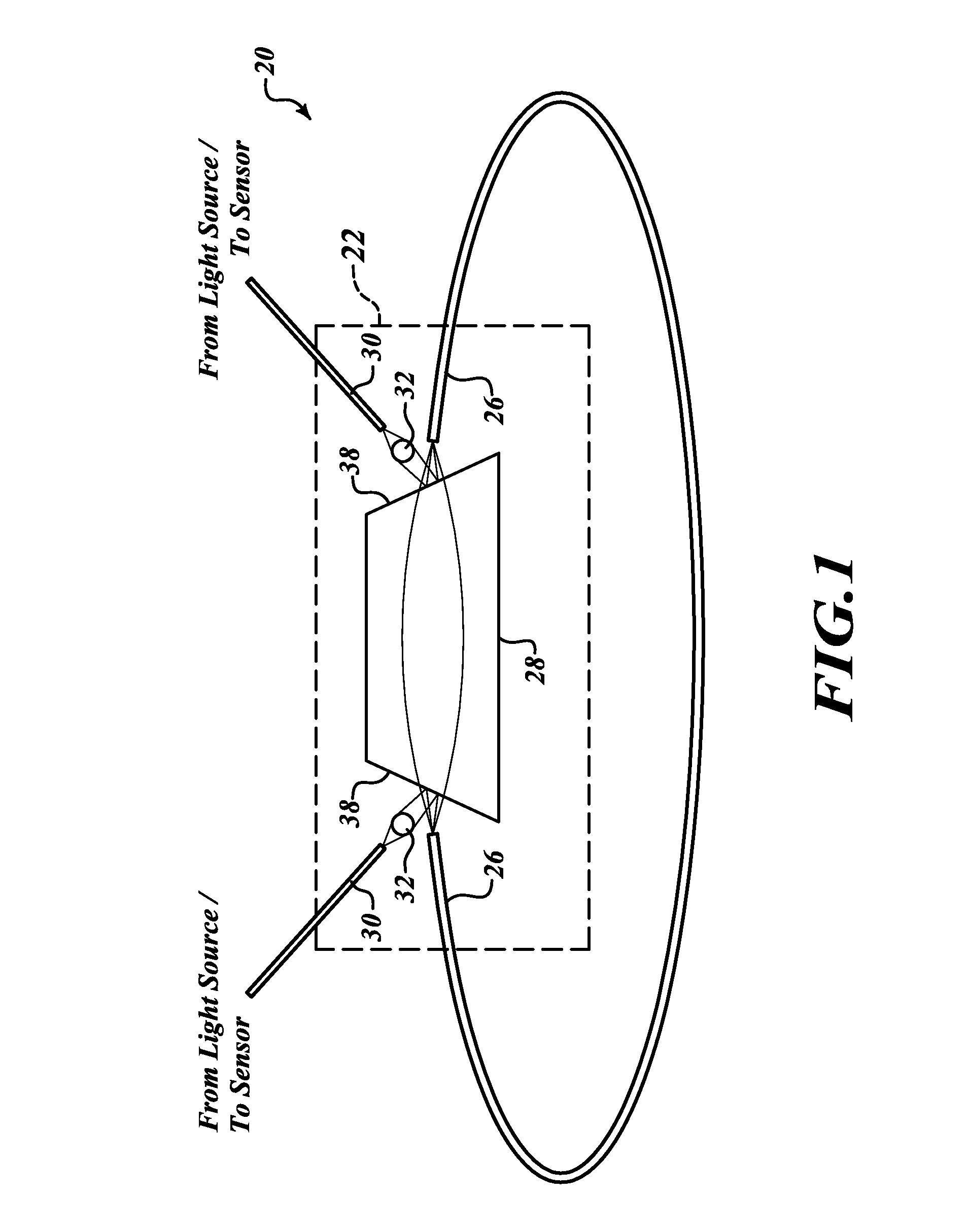
[0010]FIG. 1 illustrates a partial view of an optical ring resonator sensing device 20 formed in accordance with an embodiment of the present invention. The resonator sensing device 20 includes a resonator fiber 26, second and third (non-resonator) fibers 30, first and second microlenses 32, a graded index (GRIN) lens 28 and a package 22. The package 22 holds the fibers 30, microlenses 32, resonator fiber 26 and GRIN lens 28 in a precise configuration, such that light that comes out of one of the fibers 30 from a light source, such as a laser diode (not shown), is focused by the microlens 32 then reflected off of the GRIN lens 28 and into the ends of the resonator fiber 26.

[0011]The GRIN lens 28 is sized and optically-configured in order to allow light to pass between each end of the fiber 26, forming a resonator (closed optical loop) that includes the GRIN lens 28 and the optical fiber 26. At resonance, on average, an optical photon will make multiple round-trips around the resonat...


PUM


Abstract

A resonator sensing device having an optics coupler device for communicating light between light source(s) and sensor(s) and a hollow core fiber resonator. Light from one resonator fiber tip is coupled to a second resonator fiber tip via a graded index (GRIN) lens having the appropriate pitch such that the maximum coupling efficiency is achieved and having two angled surfaces. The angled surfaces are coated with an appropriate coating having a reflectance R in order to achieve the desired degree of coupling. Light reflected by the second angled surface is captured with another lens (such as a microlens) and coupled to a third fiber segment (coupled port). The optical parameters for the GRIN lens and the microlens are tailored to have the least loss.

Description

BACKGROUND OF THE INVENTION[0001]Photonic bandgap fiber, including hollow core fiber, has the potential to replace conventional solid core optical fiber in numerous applications. Optical components utilizing this class of fiber are limited at this time.[0002]Conventional couplers fall into three main classes: fused; lapped; and micro-optics. Micro-optic couplers are employed to split / combine two different wavelengths such as in a Wavelength Division Multiplexer or to split / combine orthogonal polarization states. Fused and lapped couplers are most commonly used for optical power redistribution.[0003]There is an immediate need for a low loss coupler having hollow core fiber as a major component for resonator sensing applications.SUMMARY OF THE INVENTION[0004]The present invention is an optical coupler that falls outside of the fused and lapped coupler classes in that it employs reflection rather than evanescent wave coupling to redistribute the optical power.[0005]The present inventio...

Claims


Application Information

Patent Timeline
IPC IPC(8): G02B6/32
CPCG02B6/2804G02B6/322G02B6/2934
Inventor DANG, THIENSANDERS, GLEN A.SPICER, TIM
Owner HONEYWELL INT INC
Why Eureka
Try Eureka