Variable-flow-rate valve mechanism and turbocharger

a variable-flow-rate valve and valve mechanism technology, which is applied in the direction of combustion engines, machines/engines, engine fuctions, etc., can solve the problems of vibrational contact, affecting the assembly performance deteriorating the quietness of the waste gate valve, so as to reduce the noise of chattering, improve the quietness of the variable-flow-rate valve mechanism, and suppress the occurrence of vibrational conta

Active Publication Date: 2019-02-26
IHI CORP
View PDF29 Cites 1 Cited by
  • Summary
  • Abstract
  • Description
  • Claims
  • Application Information

AI Technical Summary

Benefits of technology

[0013]According to the present disclosure, it is possible to provide a variable-flow-rate valve mechanism, for example, which is capable of improving quietness of the turbocharger by reducing chattering noise from the variable-flow-rate valve mechanism while suppressing an influence on the assembly performance of the variable-flow-rate valve mechanism.
[0016]According to the first aspect of the present disclosure, while the turbocharger is in operation, the link member is driven by the actuator to swing in the forward direction. Thus, the valve swings in the forward direction through the stem and the attachment member, thereby opening the aperture of the variable-flow-rate gas passage. As a consequence, when the variable-flow-rate gas passage is the bypass passage, for example, the flow rate of the exhaust gas to be supplied to the turbine wheel side can be reduced.
[0017]Meanwhile, after the aperture of the variable-flow-rate gas passage is opened, the link member is driven by the actuator to swing in the reverse direction. Thus, the valve swings in the reverse direction through the stem and the attachment member, thereby closing the aperture of the variable-flow-rate gas passage. As a consequence, when the variable-flow-rate gas passage is the bypass passage, for example, the flow rate of the exhaust gas to be supplied to the turbine wheel side can be increased (ordinary operation of the variable-flow-rate valve mechanism).
[0019]The one end portion of the leaf spring is fixed or pressed to the leading end portion of the attachment member, and the other end portion of the leaf spring is pressed to the head portion of the valve body. Otherwise, the one end portion of the leaf spring is fixed or pressed to the stopping member and the other end portion of the leaf spring is pressed to the leading end portion of the attachment member. Thus, it is possible to suppress an increase in the number of joining positions (fixing positions) by welding and the like in the variable-flow-rate valve mechanism. In the meantime, the cutout portion and the insertion hole are formed in the two end portions of the leaf spring, respectively. The valve shaft is inserted into the cutout portion and the insertion hole. Thus, the leaf spring can be easily attached to the valve shaft (characteristic operation of the variable-flow-rate valve mechanism).
[0022]According to the present disclosure, when the aperture of the variable-flow-rate passage starts opening or immediately before the aperture completes closing, it is possible to suppress occurrence of vibrational contact between the valve and the valve seat in the vicinity of the stem attributed to pulsations of the exhaust gas from the engine side, and the like. In this way, it is possible to reduce chattering noise (contact noise due to the vibrations) from the variable-flow-rate valve mechanism, and thus to improve quietness of the variable-flow-rate valve mechanism, or in other words, quietness of the turbocharger. In addition, the leaf spring can be easily attached to the valve shaft while suppressing the increase in the number of joining positions by welding and the like on the variable-flow-rate valve mechanism. This makes it possible to keep time spent on assembling the variable-flow-rate valve mechanism from being prolonged and thus to suppress an influence on an assembly performance of the variable-flow-rate valve mechanism. In other words, according to the present disclosure, the quietness of the turbocharger can be improved by reducing the chattering noise from the variable-flow-rate valve mechanism while suppressing the influence on the assembly performance of the variable-flow-rate valve mechanism.

Problems solved by technology

For this reason, if the valve allows for the play with the attachment member, these pulsations can possibly cause vibrational contact (contact due to vibrations) between the valve and the valve seat in the vicinity of the stem when the aperture of the bypass passage starts opening or immediately before the aperture completes closing, for example.
In this case, there is a concern that generation of chattering noise (contact noise due to the vibrations) from the waste gate valve may deteriorate quietness of the waste gate valve.
As a consequence, this configuration may affect an assembly performance of the waste gate valve due to reasons such as prolonged production time spent on assembling the waste gate valve.
The aforementioned problem occurs likewise in the case where a turbocharger such as a vehicle turbocharger is equipped with a variable-flow-rate valve mechanism other than the waste gate valve.

Method used


Image

  • Variable-flow-rate valve mechanism and turbocharger
  • Variable-flow-rate valve mechanism and turbocharger
  • Variable-flow-rate valve mechanism and turbocharger

Examples


first embodiment

Modified Example of First Embodiment

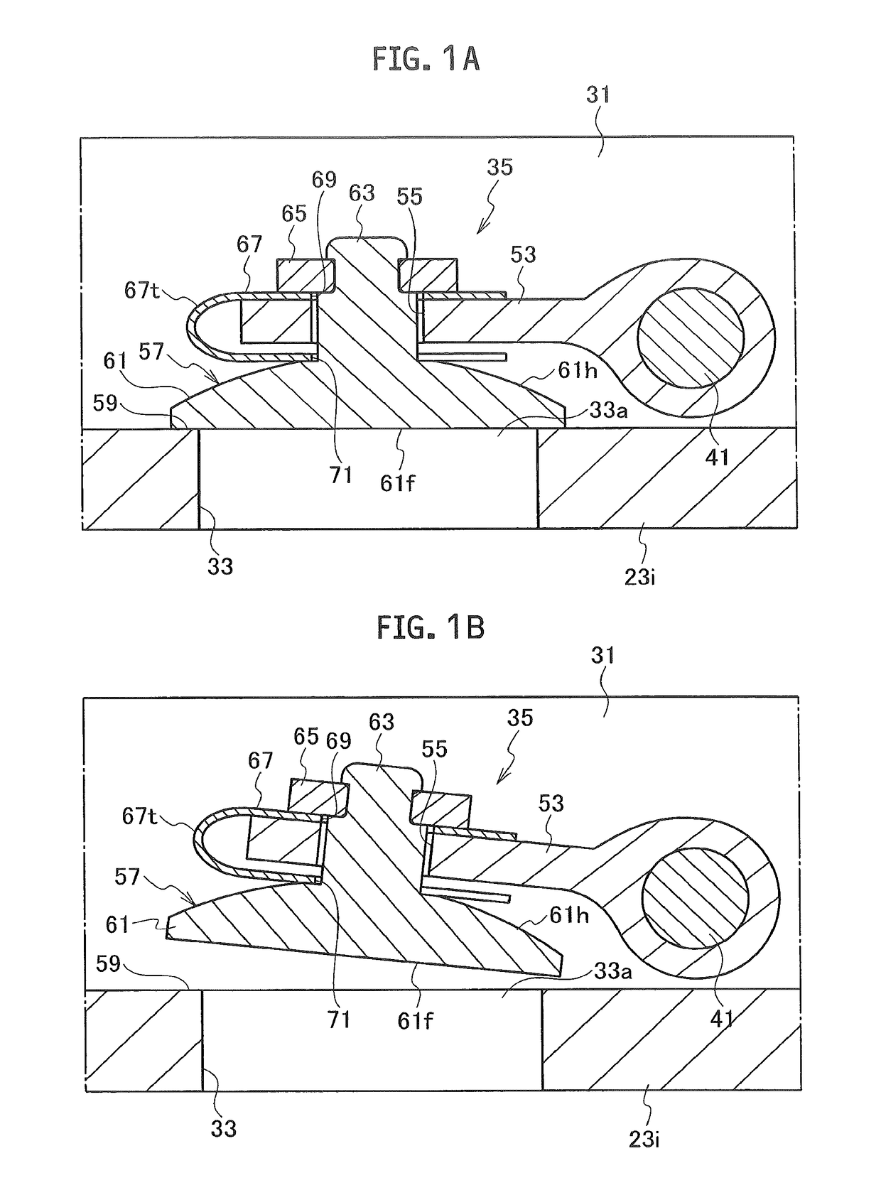
[0053]As shown in FIGS. 7A and 7B, in a modified example of the first embodiment of the present disclosure, instead of the configuration in which the one end portion of the leaf spring 67 is located between the leading end portion of the attachment member 53 and the stopping member 65 and is fixed to the attachment member 53 (see FIG. 1A), the one end portion of the leaf spring 67 is located between the leading end portion of the attachment member 53 and the head portion 61h of the valve body 61 and is pressed to the attachment member 53 by the elastic force of the leaf spring 67. Here, among the multiple constituents of the modified example of the first embodiment, those corresponding to the constituents of the first embodiment are denoted by the same reference signs in the drawings.

[0054]The modified example of the first embodiment also achieves the same operation and effect as the first embodiment does.

[0055]Although the illustration is omitted...

second embodiment

[0056]As shown in FIGS. 8A, 8B, and 9, in a second embodiment of the present disclosure, the vehicle turbocharger 1 is equipped with a different waste gate valve 73 instead of the waste gate valve 35 (see FIG. 1). The waste gate valve73 according to the second embodiment has a similar configuration to that of the waste gate valve 35 according to the first embodiment. A description will be given below only of portions of the configuration of the waste gate valve 73 which are different from those of the waste gate valve 35. Here, among multiple constituents of the second embodiment, those corresponding to the constituents of the first embodiment are denoted by the same reference signs in the drawings.

[0057]As shown in FIGS. 8A, 8B, and 10, a base end portion of an attachment member 75 is integrally connected by fillet welding or the like to the leading end portion of the stem 41. The attachment member 75 includes a folded-back portion 75t on its middle side, which is manufactured by p...


PUM


Abstract

In a variable-flow-rate valve mechanism, a valve is fitted into an attachment hole of an attachment member. The valve allows for play with the attachment member, and includes a valve body provided with a valve surface. A valve shaft is integrally formed in the center of a head portion of the valve body. A stopping member is provided to a leading end portion of the valve shaft. A leaf spring is provided to the valve shaft. The leaf spring includes a folded-back portion formed by bending. An insertion hole is formed in one end portion of the leaf spring. A cutout portion is formed in another end portion of the leaf spring. The one end portion of the leaf spring is fixed to the attachment member and the other end portion of the leaf spring is pressed to the head portion of the valve body.

Description

CROSS REFERENCE TO RELATED APPLICATIONS[0001]This application is a continuation application of International Application No. PCT / JP2015 / 070926, filed on Jul. 23, 2015 which claims priority to Japanese Patent Application No. 2014-176202, filed on Aug. 29, 2014 the entire contents of which are incorporated by reference herein.BACKGROUND[0002]1. Technical Field[0003]The present disclosure relates to a variable-flow-rate valve mechanism and the like, which opens and closes an aperture of a variable-flow-rate gas passage in order to adjust a flow rate of an exhaust gas to be supplied to a turbine wheel side in a turbocharger such as a vehicle turbocharger.[0004]2. Description of the Related Art[0005]In a turbine housing of a vehicle turbocharger, a bypass passage for causing part of an exhaust gas to bypass a turbine wheel is usually formed as a countermeasure for suppressing an excessive rise in boost pressure by the vehicle turbocharger. Moreover, a waste gate valve configured to open ...

Claims


Application Information

Patent Timeline
Patent Type & Authority Patents(United States)
IPC IPC(8): F02B37/18F01D17/10
CPCF02B37/186F01D17/105F02B37/183Y02T10/144F05D2260/38F05D2260/606F05D2260/96F05D2220/40Y02T10/12
Inventor UNEURA, YUTAKAHUH, JAEMIN
Owner IHI CORP
Why Eureka
Try Eureka