
Magnification device and assembly

a technology of magnification device and assembly, which is applied in the field of optical magnification device, can solve the problems of cumbersome or uncomfortable current-available devices, damage to the retina, and high collimation of ultraviolet light (or electromagnetic radiation) emitted from leds,

Active Publication Date: 2019-02-26
DESIGNS FOR VISION
View PDF20 Cites 15 Cited by
  • Summary
  • Abstract
  • Description
  • Claims
  • Application Information

AI Technical Summary

Benefits of technology

The invention is a magnification device that includes a housing with objective lenses and eye lenses, as well as a filtering system with two filter lenses that have different optical densities based on the desired level of magnification. The device can be attached to a carrier device for easy use. The technical effect of the invention is to provide a convenient and effective way to enhance vision, making it easier to see details and objects at a closer distance.

Problems solved by technology

However, the UV light (or electromagnetic radiation) emitted from an LED may be extremely intense and highly collimated.
However, exposure to light in the UV, (1 to 400 nm), visible (400 nm to 700 nm) and near-infrared (700 nm to 1400 nm) regions of the spectrum (retinal hazard region) may damage the retina, particularly when viewed through magnifying optical devices, as the energy of the light being viewed through the magnifying devices concentrate and increase the viewed light.
Since LEDs may radiate at more than one wavelength, eyewear designed to have an adequate OD (optical density) of a particular wavelength may have an inadequate OD at another wavelength for light emitted by the same LED.
Most eye protection glasses or goggles use selective wavelength attenuation to protect eyes from harmful LED radiation while permitting the eyes to see something of interest, by filtering radiation inside and outside the visible range, yet many of the currently-available devices are cumbersome or uncomfortable when used in conjunction with an optical magnifying device.

Method used


Image

  • Magnification device and assembly
  • Magnification device and assembly
  • Magnification device and assembly

Examples


Embodiment Construction

[0029]As used herein, the terms “comprises”, “comprising”, “includes”, “including”, “has”, “having”, or any other variation thereof, are intended to cover non-exclusive inclusions. For example, a process, method, article or apparatus that comprises a list of elements is not necessarily limited to only those elements but may include other elements not expressly listed or inherent to such process, method, article, or apparatus. In addition, unless expressly stated to the contrary, the term “of” refers to an inclusive “or” and not to an exclusive “or”. For example, a condition A or B is satisfied by any one of the following: A is true (or present) and B is false (or not present); A is false (or not present) and B is true (or present); and both A and B are true (or present).

[0030]The terms “a” or “an” as used herein are to describe elements and components of the invention. This is done for convenience to the reader and to provide a general sense of the invention. The use of these terms ...


PUM


Abstract

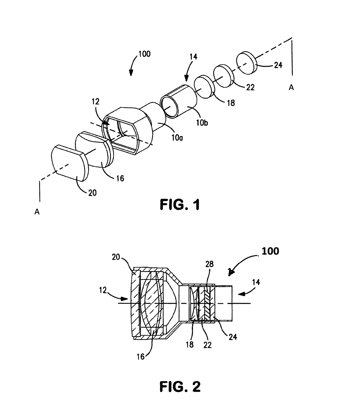
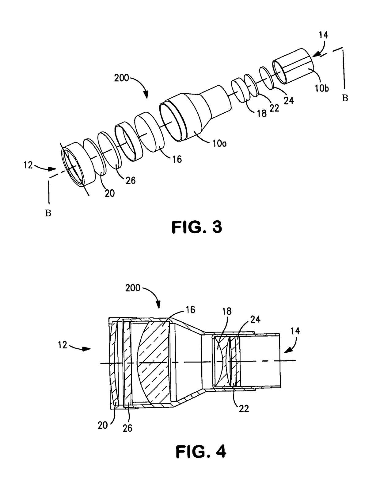
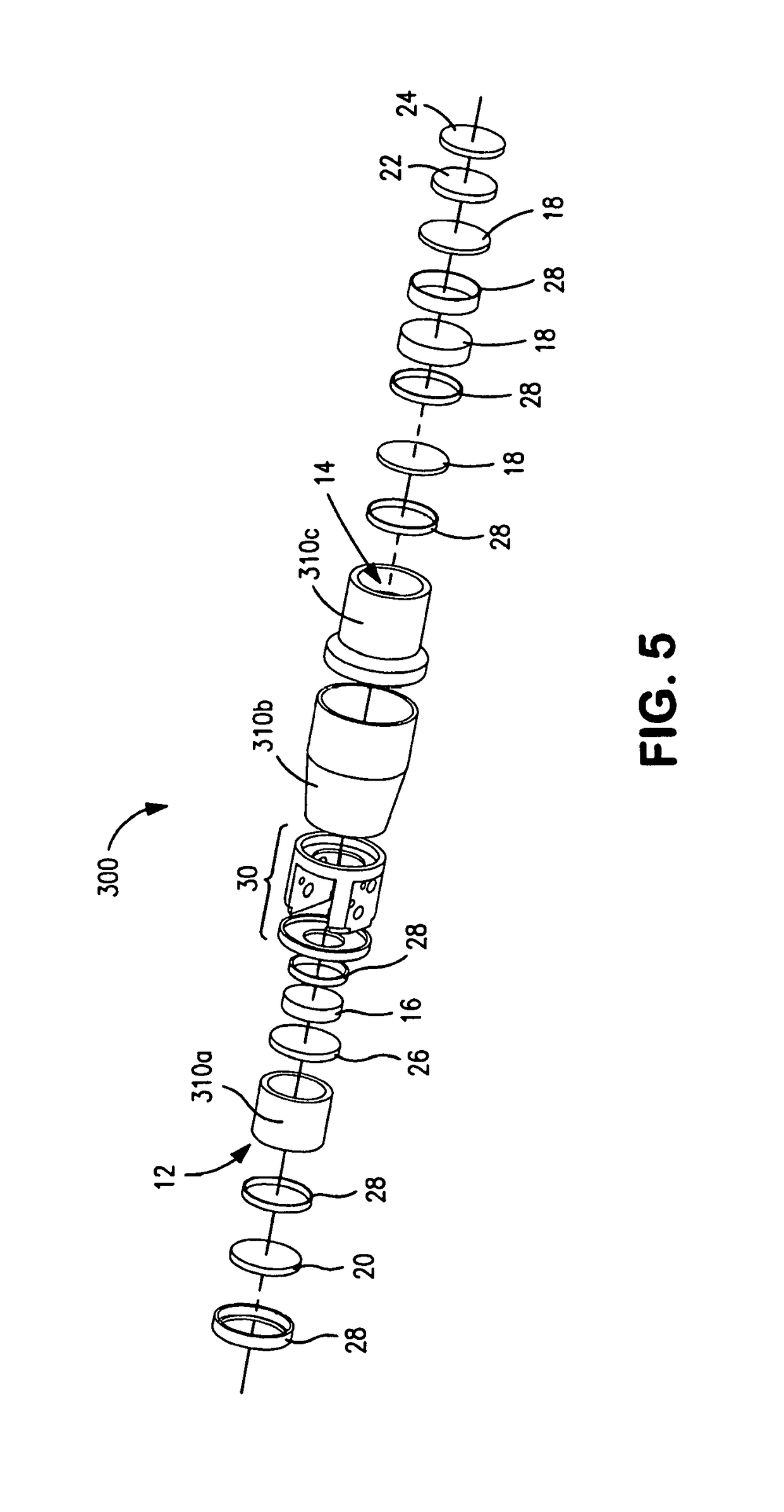
A magnification device including a housing having a distal open end and a proximal open end is disclosed. The housing includes an optical system including one or more objective lenses adjacent the distal open end, and one or more eye lenses adjacent the proximal open end, the optical system produced a desired level of magnification; and a filtering system having first filter selectively filtering a first group of wavelengths and a second filter selective filtering a second group of wavelengths. The first and second filters having an optical density selected based on a magnification level of the optical system. A vision enhancing assembly including a carrier device and one or more magnification devices coupled to the carrier device is also disclosed, wherein the magnification devices include filters that have optical densities based on a magnification level.

Description

CLAIM OF PRIORITY[0001]This application claims, pursuant to 35 USC 120, priority to, and the benefit of the earlier filing date, as a Continuation-in-part, to that application entitled “Magnification Device and Assembly,” filed on Oct. 11, 2013 and afforded Ser. No. 14 / 051,446, which claimed, pursuant to 35 USC 120, priority to, and the benefit of the earlier filing date, as a Continuation-in-part, to that application entitled “Magnification Device and Assembly,” filed on Mar. 30, 2011 and afforded Ser. No. 13 / 065,809 (abandoned), the entire contents of all of which are incorporated, herein, by reference.BACKGROUND OF THE INVENTIONField of the Invention[0002]The invention relates generally to optical devices, and more particularly, to optical magnification devices for use in the presence of a source of electromagnetic radiation.Background Information[0003]Electromagnetic radiation is currently used in a variety of fields for visualization and identification of structures. Ultra-Viol...

Claims


Application Information

Patent Timeline
Patent Type & Authority Patents(United States)
IPC IPC(8): G02B5/20G02B25/02G02B25/00G02B13/00G02B5/22G02B5/26G02B13/14
CPCG02B25/004G02B25/02G02B13/14G02B25/007G02B25/008G02B25/005G02B13/0015G02B5/22G02B5/26G02B5/208G02C7/088
Inventor FEINBLOOM, RICHARD E.STEIER, LIVIU
Owner DESIGNS FOR VISION
Learn More