Connector

a technology of connecting rods and connectors, applied in the direction of coupling device connection, coupling contact members, securing/insulating coupling parts, etc., can solve the problems of reducing and affecting the sealing state of the locking lance, etc., to achieve stable maintenance of the closing state and reinforce the deflection strength of the hing

Active Publication Date: 2019-03-05
SUMITOMO WIRING SYST LTD
View PDF12 Cites 4 Cited by
  • Summary
  • Abstract
  • Description
  • Claims
  • Application Information

AI Technical Summary

Benefits of technology

[0008]The inner housing is separate from the outer housing that has the lock arm. Thus, the inner housing can have a relatively simple structure and can deal with size reduction. On the other hand, the inner housing is structured such that the seal ring is fit behind the entrance opening. Accordingly, there is no marginal space to provide an integral retaining portion. Therefore, a merit of providing the front retainer with the retaining portion is large.
[0010]The deflection restricting portion may be thicker than the hinge. Accordingly, the deflection restricting portion is strong and can reinforce deflection strength of the hinge.
[0011]The retaining portion may include locks on both side surfaces of a locking body, and the locks may engage lock receiving portions on both side walls of the front retainer in the closing state. Accordingly, the retaining portion can stably maintain the closing state.
[0012]A seal ring may be fit on the housing and may be sandwiched between the housing and a mating housing as a connection partner in a fluid- or liquid-tight manner. The retaining portion may be arranged to contact a front end of the seal ring in the closed state. Accordingly, the retaining portion prevents forward detachment of the seal ring.
[0014]The front retainer includes the deflection restricting portion configured to restrict deflection of the locking lance and the retaining portion. A tilting movement of the retaining portion about the hinge from the opening state to the closing state laterally locks the retaining portion to the retainer receiving portion and retains the terminal fittings. Thus, rearward detachment of the terminal fitting can be reliably prevented. Further, it is not necessary to provide a dedicated retainer, such as a side retainer separately from the front retainer. Thus, the number of components can be reduced. Furthermore, the provision of the front retainer with the retaining portion makes the structure of the housing less complicated.

Problems solved by technology

Further, if the connector is reduced in size and the structure of a housing becomes complicated, a retainer cannot be made integral to the housing.
However, the locking lance may be fractured or broken if the deflection restricting portion strongly interferes with the locking lance.

Method used


Image

  • Connector
  • Connector
  • Connector

Examples


Embodiment Construction

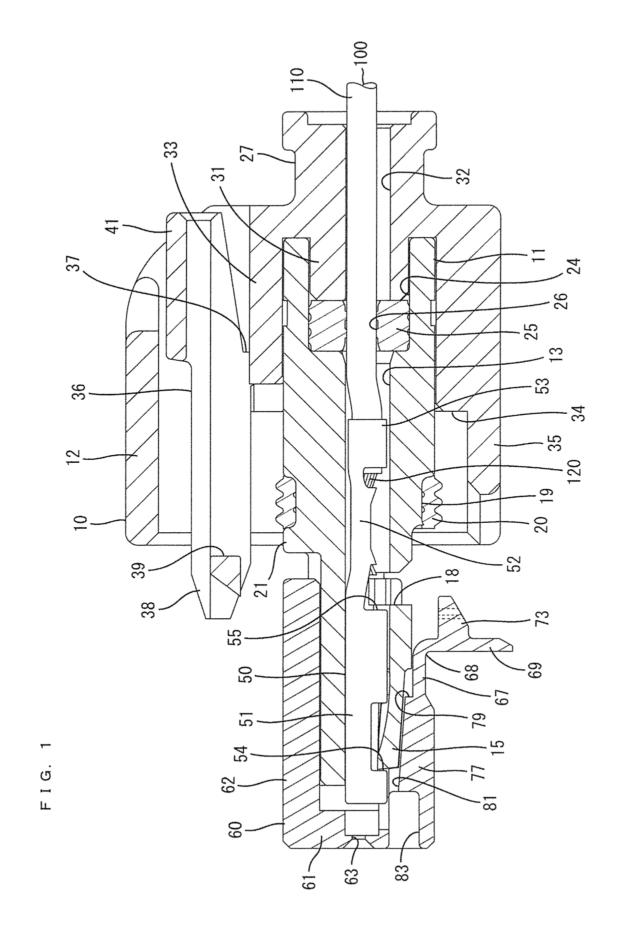
[0016]FIG. 1 is a side view in section when a front retainer is held at a partial locking position with respect to a housing and a retaining portion is in an opening state in an embodiment of the present invention.

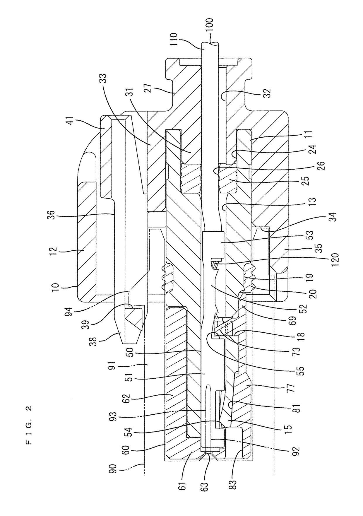
[0017]FIG. 2 is a side view in section when the front retainer is at a full locking position with respect to the housing and the retaining portion is in a closing state.

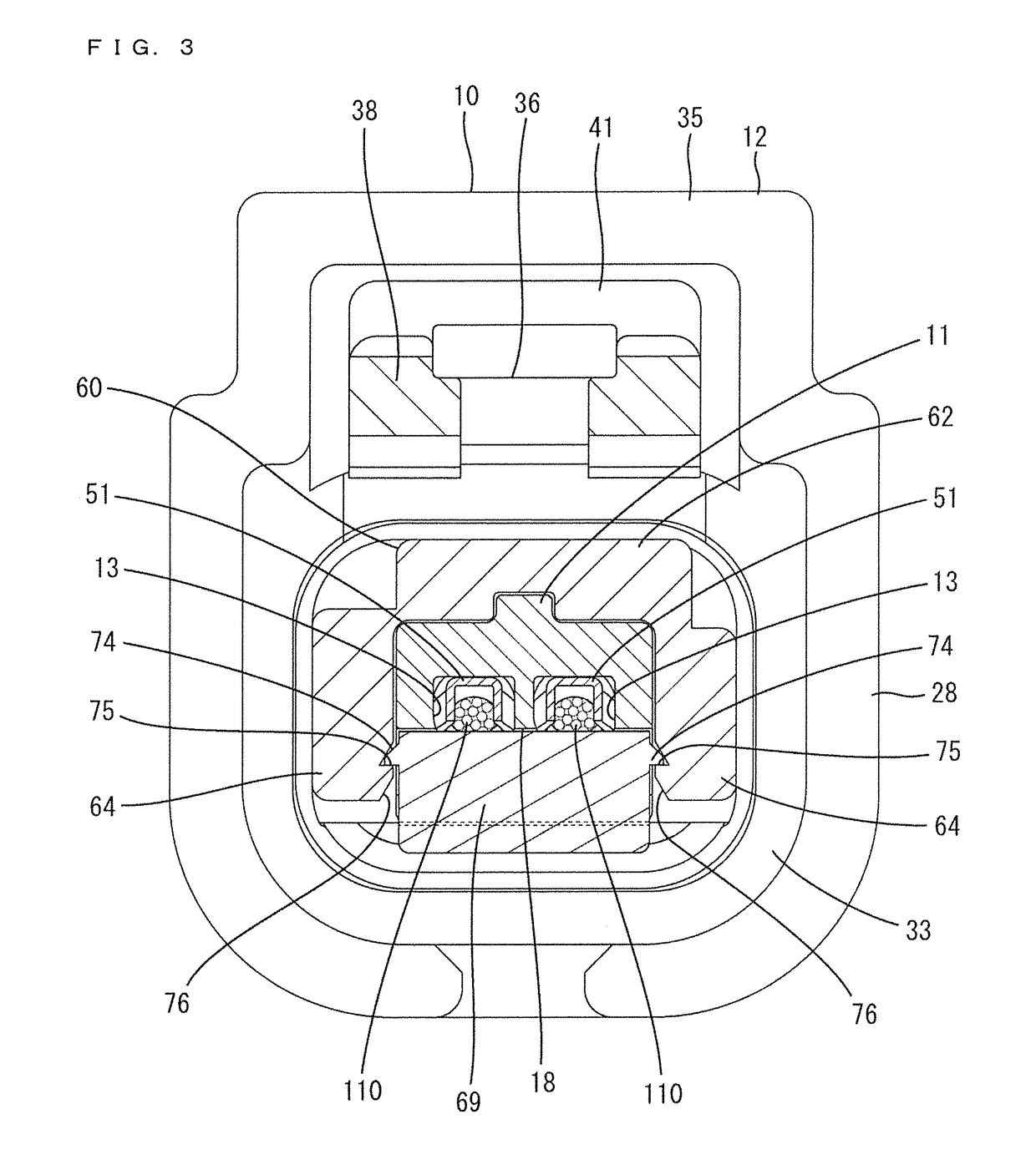
[0018]FIG. 3 is a front view in section when the front retainer is at the full locking position with respect to the housing and the retaining portion is closed.

[0019]FIG. 4 is a side view when the front retainer is at the partial locking position with respect to the housing and the retaining portion is open.

[0020]FIG. 5 is a bottom view when the front retainer is at the partial locking position with respect to the housing and the retaining portion is open.

[0021]FIG. 6 is a front view when the front retainer is at the partial locking position with respect to the housing and the retaining portion is open.

[002...


PUM


Abstract

A connector includes a housing (10) having cavities (13) and deflectable and deformable locking lances (15) project into the cavities (13), and a front retainer (60) to be mounted into the housing (10) from the front. A terminal fitting (50) is inserted into the cavity (13) of the housing (10), and the locking lance (15) resiliently locks a lance receiving portion (54) so that rearward detachment of the terminal fitting (50) is restricted. The front retainer (60) includes a deflection restricting portion (77) configured to restrict the deflection of the locking lances (15), and a retaining portion (69) configured to lock retainer receiving portions (55) and retain the terminal fittings (50) by laterally approaching the terminal fittings (50) by a tilting displacement about a hinge (68) from an opening state to a closing state.

Description

BACKGROUNDField of the Invention[0001]The present invention relates to a connector.Description of the Related Art[0002]Japanese Unexamined Patent Publication No. 2002-184506 discloses a connector with a housing having a cavity to accommodate a terminal fitting. A retainer is connected to the housing by an integral hinge and can tilt relative to the housing. A deflectable locking lance projects from an inner wall of the cavity of the housing. The terminal fitting includes a tubular connecting portion, and a lance receiving portion is open in a peripheral wall of the connecting portion. The rear end of the connecting portion serves as a retainer receiving portion. The locking lance locks the lance receiving portion of the terminal that has been inserted in the cavity to prevent the terminal fitting from coming rearward out of the cavity. Further, the retainer can close an entrance opening of the housing, and a lock of the retainer locks a rear end edge of the connecting portion to ret...

Claims


Application Information

Patent Timeline
Patent Type & Authority Patents(United States)
IPC IPC(8): H01R13/42H01R13/436H01R13/422H01R13/426H01R13/50
CPCH01R13/4223H01R13/426H01R13/4361H01R13/501H01R13/4365H01R13/4368H01R13/4364H01R13/40H01R13/46H01R13/62H01R13/639H01R13/506H01R13/5208H01R13/5221
Inventor IIDA, MASAHIRO
Owner SUMITOMO WIRING SYST LTD
Why Eureka
Try Eureka