Neutralization of charged lubricant

a technology of charged lubricant and neutralization arrangement, which is applied in the direction of instruments, mechanical equipment, material analysis, etc., can solve the problems of bearing damage, decarburization and sparking, and the solution known from the prior art is not suitable for eliminating currents

Active Publication Date: 2019-03-12
ZF FRIEDRICHSHAFEN AG +1
View PDF7 Cites 0 Cited by
  • Summary
  • Abstract
  • Description
  • Claims
  • Application Information

AI Technical Summary

Benefits of technology

[0006]The purpose of the present invention is to overcome the inadequacies and disadvantages inherent in the solutions known from the prior art. This should improve the robustness of bearings, in particular against the formation of White Etching Cracks.
[0025]The part of the first electrode immersed in the liquid and / or the part of the second electrode immersed in the liquid preferably have at least one point and preferably a plurality of point. Since the charge density is particularly high around a point, this improves the charge transfer between the first and second electrodes and the liquid.

Problems solved by technology

Electrical currents can cause damage in bearings.
It is known that currents of the order of microamperes to amperes result in decarburization and sparking.
However, the solutions known from the prior art are not suitable for eliminating currents in the microampere range.

Method used


Image

  • Neutralization of charged lubricant
  • Neutralization of charged lubricant
  • Neutralization of charged lubricant

Examples


Embodiment Construction

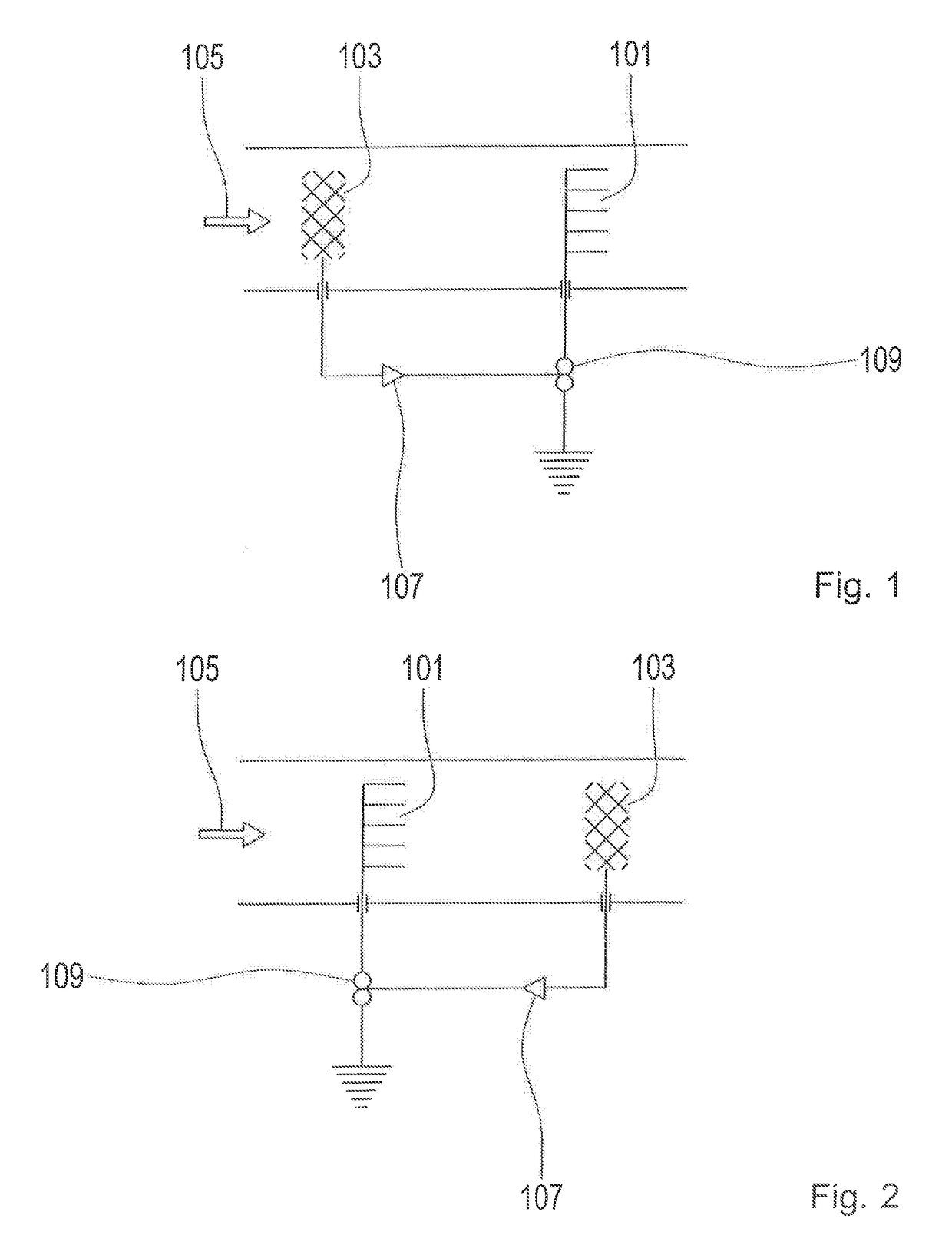
[0036]FIG. 1 shows a first electrode 101 and a second electrode 103. The first electrode 101 has a plurality of spikes. The second electrode 103 is in the form of a grid structure.

[0037]The two electrodes 101, 103 are arranged in a lubricant flow 105 in such manner that between the electrodes 101, 103 and the lubricant, a charge transfer can take place.

[0038]The first electrode 101 is electrically connected to a charge amplifier 107. This makes it possible to measure the charge of the liquid flowing past the second electrode 103.

[0039]Depending on the charge measured, the first electrode 101 has a voltage applied to it. For that purpose the first electrode 101 is electrically connected to a voltage generator 109.

[0040]Both the charge amplifier 107 and the voltage generator 109 are grounded.

[0041]In FIG. 1 the first electrode 101 is positioned downstream and the second electrode 103 upstream. An inverse arrangement is shown in FIG. 2, in which the first electrode 101 is arranged upst...


PUM

PropertyMeasurementUnit
voltageaaaaaaaaaa
electric voltageaaaaaaaaaa
electrically conductingaaaaaaaaaa

Abstract

An arrangement with a first electrode (101), a second electrode (103), at least one measuring device (107) and at least one voltage source (109). The voltage source (109) is designed to apply a first electric voltage to the first electrode (101) and the measuring device (107) is designed to measure a second electric voltage at the second electrode (103). At least part of the first electrode (101) and at least part of the second electrode (103) are immersed in a flowing liquid.

Description

[0001]This application claims priority from German patent application serial no. 10 2016 211 615.0 filed Jun. 28, 2016.FIELD OF THE INVENTION[0002]The invention concerns an arrangement for neutralizing a charged lubricant.BACKGROUND OF THE INVENTION[0003]Electrical currents can cause damage in bearings. It is known that currents of the order of microamperes to amperes result in decarburization and sparking.[0004]From the prior art oil filters are available, which are intended to prevent the lubricant to be filtered from becoming electrically charged. Such a filter is described, for example, in the document DE 10 2010 025 215 A1.[0005]Recent research has shown that even small currents in the range of a few microamperes can be critical. It is suspected that such currents give rise to so-termed White Etching Cracks (WEC). However, the solutions known from the prior art are not suitable for eliminating currents in the microampere range.SUMMARY OF THE INVENTION[0006]The purpose of the pr...

Claims


Application Information

Patent Timeline
Patent Type & Authority Patents(United States)
IPC IPC(8): G01N27/60G01R19/00G01N33/28G01R19/165F16C19/52F16C41/00
CPCG01N27/60F16C19/52F16C41/00G01N33/2888G01R19/0069G01R19/16504G01N33/28F16C2360/31
Inventor TENCKHOFF, GEORGENGELEN, KURTMARTIN BARRIOS, ALEJANDRO
Owner ZF FRIEDRICHSHAFEN AG
Why Eureka
Try Eureka