Woven fabric

a technology of woven fabric and woven fabric, which is applied in the direction of fibre light guides, lighting and heating devices, instruments, etc., can solve the problems of reducing the designability of woven fabric and indistinct light emission parts, and achieve the effect of reducing the designability of woven fabric and even light emission reduction

Active Publication Date: 2019-03-12
TOYOTA BOSHOKU KK +1
View PDF23 Cites 0 Cited by
  • Summary
  • Abstract
  • Description
  • Claims
  • Application Information

AI Technical Summary

Benefits of technology

[0005]The fabric having the optical fibers described in JP 2006-39287 A, is useful, for example, as automobile accessories such as interior decoration goods. In the optical fiber woven fabric described in JP 2010-267573 A, uneven light emission can be reduced by controlling the woven texture and emission luminance to be in predetermined states. JP 2006-39287 A and JP 2010-267573 A however, nowhere mention that the leakage of light from the circumferential edge part renders the dot-shaped light emission part indistinct and reduces the designability of the woven fabric.
[0006]The present invention has been made in light of the above-mentioned conventional art situations. An object of this invention is to provide a woven fabric which is woven from a side emission type optical fiber and a light shielding yarn or the like constituting a light shielding structure for suppressing leakage of light from a circumferential edge part of a light emission part by this side emission type optical fiber and which has a distinct light emission part and thus can improve the designability in vehicle compartments when used, for example, as a skin material for vehicle interior.
[0020]In the woven fabric of the present invention, a part of the first constituent yarns are side emission type optical fibers and at least a part of the second constituent yarns are light shielding yarns. The woven fabric has a light shielding structure which is formed of the following: a first group of light shielding yarns and a second group of light shielding yarns, each formed of the 2 to 4 continuous light shielding yarns intersecting the side emission type optical fiber on the design surface side; and the one light shielding yarn arranged between the first group of light shielding yarns and the second group of light shielding yarns and intersecting the side emission type optical fiber on the non-design surface side. This light shielding structure is arranged at a circumferential edge part of a light emission part formed of the side emission type optical fiber, thereby making it possible to suppress leakage of light from the circumferential edge part, to provide more distinct light emission from the light emission part, and to form the intended design surface.
[0021]Also, when a light emission part is formed between the light shielding structures and, in the light emission part, the 4 to 8 continuous light shielding yarns intersect the side emission type optical fiber on the non-design surface side, a dot-shaped distinct light emission part can be formed. A required number of the light emission parts are formed at predetermined positions, thereby making it possible to provide regularly aligned dot-shaped light emission parts and to form a design surface which offers a relaxed atmosphere. On the other hand, the dot-shaped light emission parts can also be used to form a design surface having a specific pattern.
[0023]Also, when the number of the plurality of the light shielding structures arranged continuously is 2 to 6, the leakage of light can be suppressed more sufficiently, and the intervals between the respective dot-shaped light emission parts can be made preferable from the viewpoint of designability.
[0025]Further, in the case where 1 / 1 woven textures of the side emission type optical fiber and the light shielding yarns are connected to both side parts of a site in which the 4 to 8 continuous light shielding yarns intersect the side emission type optical fiber on the non-design surface side and where the site is used as a pale-color light emission part, the distinct light emission parts and the pale-color light emission parts are arranged at desired positions, thereby enabling a wide range of designability expressions.

Problems solved by technology

JP 2006-39287 A and JP 2010-267573 A however, nowhere mention that the leakage of light from the circumferential edge part renders the dot-shaped light emission part indistinct and reduces the designability of the woven fabric.

Method used


Image

  • Woven fabric
  • Woven fabric
  • Woven fabric

Examples


Embodiment Construction

[0032]Hereinafter the present invention will be described in detail with reference to the drawings.

[0033]The particulars shown herein are by way of example and for purposes of illustrative discussion of the embodiments of the present invention only and are presented in the cause of providing what is believed to be the most useful and readily understood description of the principles and conceptual aspects of the present invention. In this regard, no attempt is made to show structural details of the present invention in more detail than is necessary for the fundamental understanding of the present invention, and the description is taken with the drawings making apparent to those skilled in the art how the forms of the present invention may be embodied in practice.

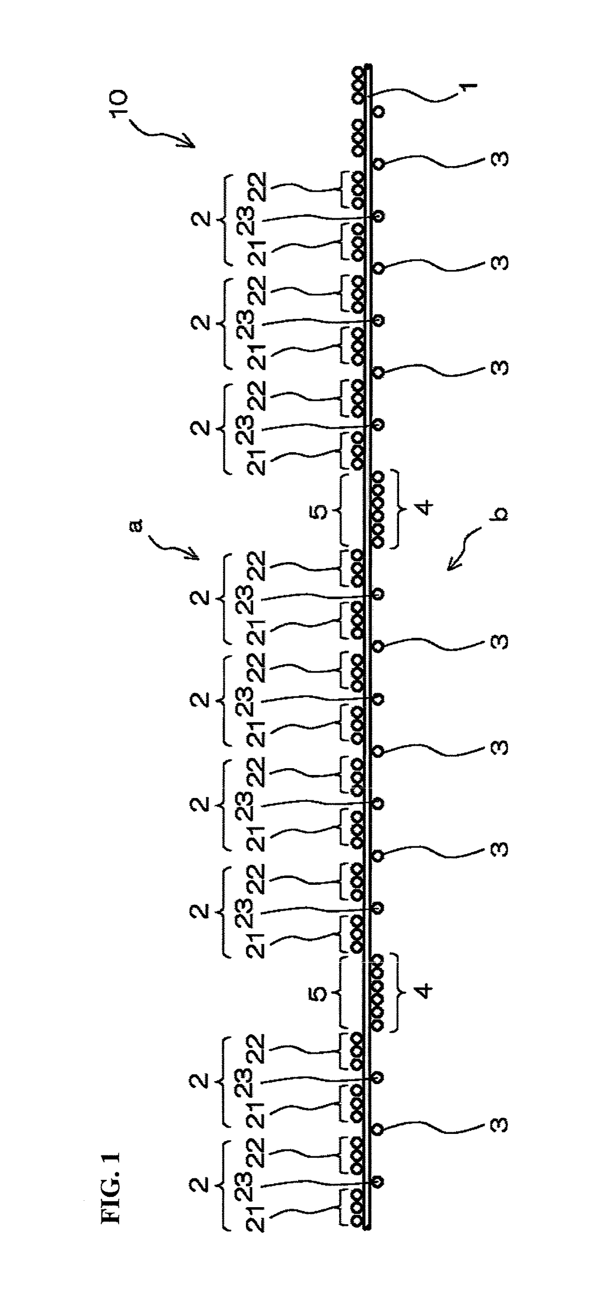
[0034]A woven fabric 10 of the present invention is a woven fabric 10 woven from first constituent yarns as one of warps and wefts and second constituent yarns as the other. Also, a part of the first constituent yarns are sid...


PUM

PropertyMeasurementUnit
friction coefficientaaaaaaaaaa
diameteraaaaaaaaaa
diameteraaaaaaaaaa

Abstract

In a woven fabric woven from first constituent yarns as one of warps and wefts and second constituent yarns as the other, a part of the first constituent yarns are side emission type optical fibers; at least a part of the second constituent yarns are light shielding yarns; the woven fabric has a light shielding structure which shields light emission on a design surface side of the side emission type optical fiber; the light shielding structure includes a first group of light shielding yarns and a second group of light shielding yarns each formed of the 2 to 4 continuous light shielding yarns intersecting the side emission type optical fiber on the design surface side; the one light shielding yarn arranged between the first group of light shielding yarns and the second group of light shielding yarns and intersecting the side emission type optical fiber on a non-design surface side.

Description

CROSS-REFERENCE TO RELATED APPLICATIONS[0001]The present application claims priority under 35 U.S.C. § 119 of Japanese Application No. 2016-106298 filed on May 27, 2016, the disclosure of which is expressly incorporated by reference herein in its entirety.BACKGROUND1. Technical Field[0002]The present invention relates to a woven fabric which is woven from a side emission type optical fiber and a light shielding yarn or the like constituting a light shielding structure for suppressing leakage of light from a circumferential edge part of a light emission part by this side emission type optical fiber and which has a distinct light emission part and thus can improve the designability in vehicle compartments when used, for example, as a skin material for vehicle interior.2. Related Art[0003]The use of optical fibers is expanding in technical fields of optical communication and the like along with popularization or the like of the Internet. Based on the feature of optical fibers that they...

Claims


Application Information

Patent Timeline
Patent Type & Authority Patents(United States)
IPC IPC(8): D03D15/00G02B6/25D02G3/44F21V8/00G02B6/24D03D13/00D03D25/00D02G1/18
CPCG02B6/25D02G3/446D03D15/00G02B6/001G02B6/24D02G3/44D03D13/004D10B2401/20F21V2200/15D02G1/18D10B2101/06D03D15/41D03D15/547D03D15/283
Inventor YAMADA, TAKAMASAITO, ATSUHIKOYAMAMOTO, TAKAYOSHI
Owner TOYOTA BOSHOKU KK
Why Eureka
Try Eureka