Labor-saving push-button water valve

a technology of push-button water valve and push-button, which is applied in the direction of valve operating means/releasing devices, functional valve types, mechanical apparatus, etc., can solve the problems of the above-mentioned push-button water saving structure, and achieve the effects of reducing the friction between the valve core and the peripheral wall of the core chamber, reducing the friction, and reducing the friction

Active Publication Date: 2019-03-19
PURITY XIAMEN SANITARY WARE
View PDF10 Cites 27 Cited by
  • Summary
  • Abstract
  • Description
  • Claims
  • Application Information

AI Technical Summary

Benefits of technology

[0017]When the button is pressed down, the button pushes the valve core to move forward in the core chamber and the valve core spring is compressed. The water inlet hole and the water outlet hole of the peripheral wall of the core chamber are not communicated with each other. The water at one end of the water inlet hole cannot reach the water outlet hole through the water chamber. At this moment, the annular groove of the valve core is communicated with the water inlet hole so that the water from the water inlet hole to the valve core is to fill the annular groove. The annular groove forms the annular hydraulic chamber. The water in the annular hydraulic chamber applies a force towards the axial center of the valve core in a 360-degree manner so that there is no pressure difference in all directio

Problems solved by technology

The disadvantage of the aforesaid push-butto

Method used


Image

  • Labor-saving push-button water valve
  • Labor-saving push-button water valve
  • Labor-saving push-button water valve

Examples


Embodiment Construction

[0031]Embodiments of the present invention will now be described, by way of example only, with reference to the accompanying drawings.

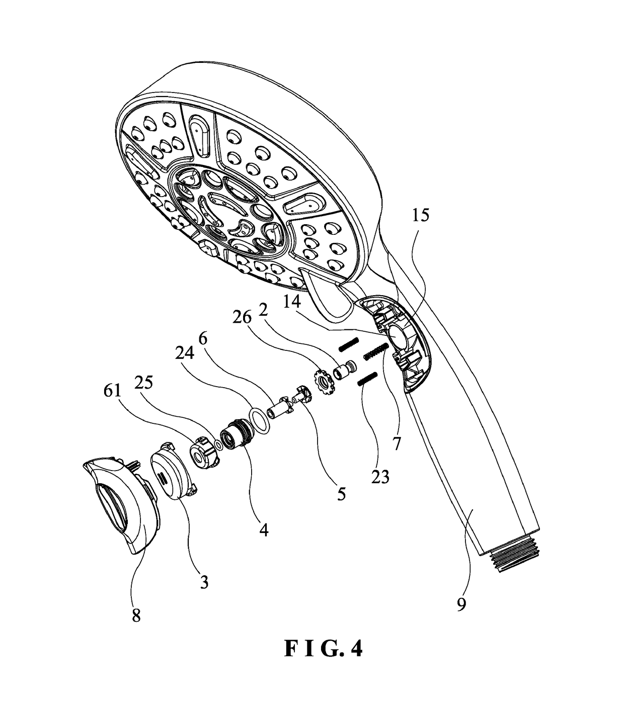
[0032]As shown in FIG. 4 to FIG. 14, the present invention discloses a labor-saving push-button water valve comprising a valve core 2, a button 3, a valve core spring 7, and a valve seat 15. Wherein, the valve seat 15 is formed on a side wall of a water inlet assembly 1. The water inlet assembly 1 is formed with a water inlet passage 11 in the water inlet assembly 1. In this embodiment, the water inlet assembly 1 is a water inlet pipe. The middle portion of the valve seat 15 is formed with a core chamber 14. The core chamber 14 is divided into a front section and a rear section to communicate with each other. The front section is a water chamber 141 extending from the side wall of the water inlet assembly 1 to the water inlet passage 11. The rear section is a drive chamber 142 extending to the outside of the water inlet assembly 1. The valve core 2 is...


PUM


Abstract

A labor-saving push-button water valve includes a button, a valve core, a valve core spring, and a valve seat. The middle portion of the valve seat is formed with a core chamber. An outer periphery of a front end of the valve core is formed with an annular groove. When the button drives the valve core to move to the position where a water inlet hole is not communicated with a water outlet hole, an annular hydraulic chamber is formed between the valve core and the peripheral wall of the core chamber. The water valve is able to switch the opening and closing of the waterway smoothly by reducing the water pressure applied to the valve core, and reduces the wear of the valve core, and improves the service life and the airtightness of the water saving structure.

Description

BACKGROUND OF THE INVENTION1. Field of the Invention[0001]The present invention relates to a bathroom accessory, and more particularly to a labor-saving push-button water valve.2. Description of the Prior Art[0002]As shown in FIG. 1 to FIG. 3, a conventional push-button water saving structure in the bathroom industry comprises a water inlet assembly 10, a spring 20, a valve core assembly 30, an O-shaped ring 40, an O-shaped ring 50, a fixing seat 60, a button 70, and a decorative cover 80. The valve core assembly 30 includes a first intermediate member 301, a second intermediate member 302, and a valve core 303. The fixing seat 60 is inserted into a water inlet passage of the water inlet assembly 10 from the side of the water inlet assembly. The valve core 303 is movably disposed in the fixing seat 60 and can be moved along the axial direction. Two sides of the fixing seat 60 are formed with a water inlet hole 601 corresponding to a water inlet end of the water inlet assembly 10 and...

Claims


Application Information

Patent Timeline
IPC IPC(8): F16K31/60B05B1/30F16K21/12B05B1/16F16K21/02B05B1/18
CPCB05B1/30F16K31/602F16K21/02B05B1/1663F16K21/12B05B1/18F16K31/52408F16K31/56B05B1/3026B05B12/002
Inventor YANG, XIWEN
Owner PURITY XIAMEN SANITARY WARE
Why Eureka
Try Eureka