Rotating electric machine

a technology of rotating electric machines and rotating shafts, which is applied in the direction of dynamo-electric machines, electrical apparatus, and control/drive circuits, etc., can solve the problems of limiting the characteristics affecting the operation of rotating electric machines, and occupying a large space for receiving windings, so as to achieve the effect of reducing the size of rotating electric machines

Active Publication Date: 2019-03-19
DENSO CORP
View PDF15 Cites 0 Cited by
  • Summary
  • Abstract
  • Description
  • Claims
  • Application Information

AI Technical Summary

Benefits of technology

[0007]With the above configuration, it becomes possible to apply a field without employing brushes. Moreover, it is possible to control the field by varying the amplitude and / or direction of the DC component. In other words, it is possible to perform the field control while performing an electric drive control of the rotating electric machine by controlling the multi-phase alternating current supplied to the multi-phase coil. Consequently, it becomes possible to realize a brushless variable field without employing a field winding. Further, since no additional winding is needed for performing the field control, it becomes possible to minimize the size of the rotating electric machine. Moreover, since the field is applied by utilizing the multi-phase coil wound on the armature core, it becomes possible to secure desired characteristics of the rotating electric machine. As a result, it becomes possible to achieve both minimization of the size of the rotating electric machine and the brushless variable field.

Problems solved by technology

However, with the aforementioned permanent magnet field, it is difficult to vary the strength of field; thus losses occur and there are limits on the characteristics of the rotating electric machines.
However, the space required for receiving a winding is generally larger than that required for receiving a permanent magnet.
Consequently, a considerably large volume is required for employing the winding field.
As a result, it is difficult to achieve the original object, i.e., to achieve a small size and high permeance.

Method used


Image

  • Rotating electric machine
  • Rotating electric machine
  • Rotating electric machine

Examples


first embodiment

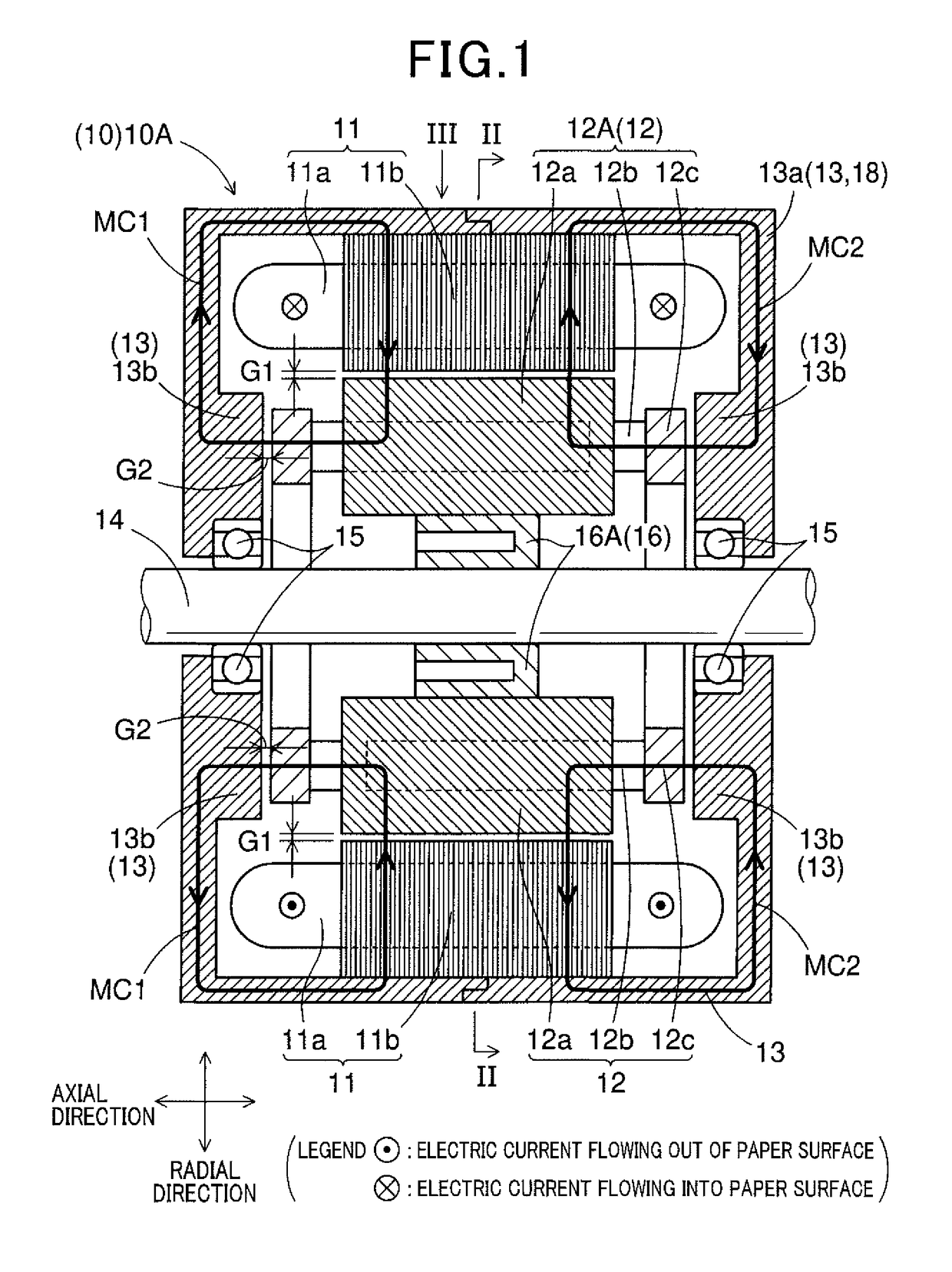
[0036]FIG. 1 shows the overall configuration of a rotating electric machine 10A according to a first embodiment. The rotating electric machine 10A is an example of a rotating electric machine 10 according to the present invention.

[0037]In addition, the rotating electric machine 10 according to the present invention may be an electric motor, an electric generator or a motor-generator that selectively functions either as an electric motor or as an electric generator.

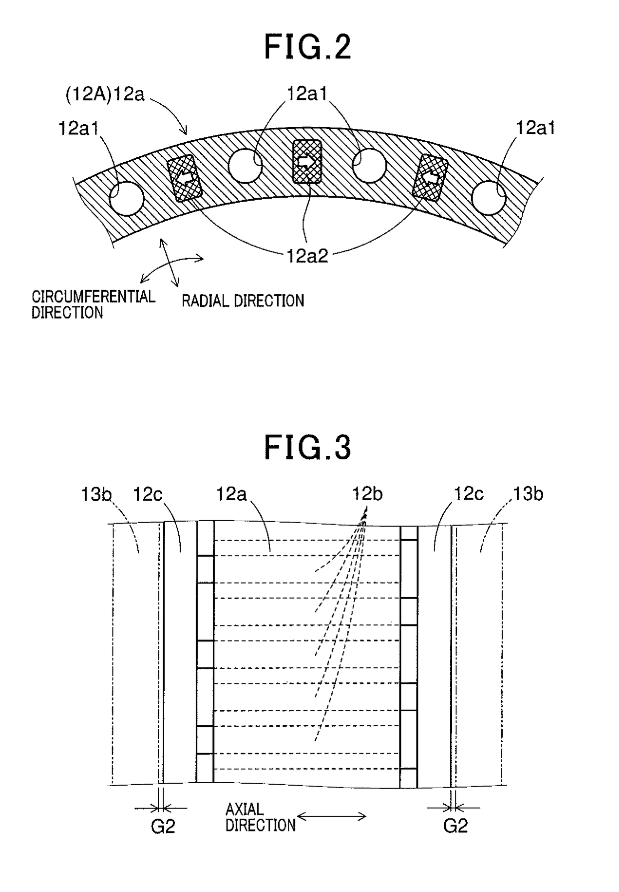
[0038]As shown in FIG. 1, the rotating electric machine 10A includes an armature (or stator) 11, a rotor 12A, a rotating shaft 14, a pair of bearings 15 and a support 16A, all of which are received in a yoke core 13.

[0039]The yoke core 13 is an example of a supporting member 18 which can be formed of any suitable material into any suitable shape. The supporting member 18 corresponds to a frame or housing and supports at least an annular armature core 11b. The yoke core 13 includes a core main body 13a and a pair of protrud...

second embodiment

[0059]A rotating electric machine 10B according to a second embodiment will be described with reference to FIGS. 7-8. The rotating electric machine 10B is another example of the rotating electric machine 10 according to the present invention.

[0060]The rotating electric machine 10B according to the present embodiment has a configuration similar to that of the rotating electric machine 10A according to the first embodiment. Accordingly, for the sake of avoiding redundancy, the differences of the rotating electric machine 10B from the rotating electric machine 10A will be mainly described.

[0061]As shown in FIG. 7, the rotating electric machine 10B according to the present embodiment includes an armature (or stator) 11, a rotor 12B, a rotating shaft 14, a pair of bearings 15 and a support 16B, all of which are received in a yoke core 13.

[0062]The support 16B is another example of the support 16 according to the present invention. In the present embodiment, the support 16B is made of a n...

third embodiment

[0070]A rotating electric machine 10C according to a third embodiment will be described with reference to FIG. 9. The rotating electric machine 10C is yet another example of the rotating electric machine 10 according to the present invention.

[0071]The rotating electric machine 10C according to the present embodiment has a configuration similar to those of the rotating electric machines 10A and 10B according to the first and second embodiments. Accordingly, for the sake of avoiding redundancy, the differences of the rotating electric machine 10C from the rotating electric machines 10A and 10B will be mainly described.

[0072]As shown in FIG. 9, the rotating electric machine 10C according to the present embodiment includes an armature (or stator) 11, a rotor 12B, a rotating shaft 14, a pair of bearings 15, a support 16C and an excitation means 17, all of which are received in a yoke core 13.

[0073]The support 16C is yet another example of the support 16 according to the present invention...


PUM


Abstract

A rotating electric machine includes a multi-phase coil, an armature core, a rotor, a yoke core and a superimposer. The armature core has the multi-phase coil wound thereon. The rotor is rotatably disposed and has a plurality of magnetic poles facing the armature core. The yoke core is arranged so as to surround outer peripheries of the multi-phase coil and the armature core. The yoke core is magnetically connected with the magnetic poles of the rotor. The superimposer superimposes a DC component on a multi-phase alternating current supplied to the multi-phase coil, thereby supplying a DC field magnetic flux to a magnetic circuit that is formed by the armature core, the magnetic poles of the rotor and the yoke core.

Description

CROSS-REFERENCE TO RELATED APPLICATION[0001]This application is based on and claims priority from Japanese Patent Application No. 2015-76088 filed on Apr. 2, 2015, the content of which is hereby incorporated by reference in its entirety into this application.BACKGROUND1 Technical Field[0002]The present invention relates to rotating electric machines which include a multi-phase coil and an armature core.2 Description of Related Art[0003]To achieve a small size, high performance, long service life and high reliability, it is general for rotating electric machines to employ a brushless structure with a permanent magnet field. On the other hand, for usage in a wide rotational speed range, it is necessary to vary the strength of field. However, with the aforementioned permanent magnet field, it is difficult to vary the strength of field; thus losses occur and there are limits on the characteristics of the rotating electric machines. Therefore, one may consider employing a winding field i...

Claims


Application Information

Patent Timeline
Patent Type & Authority Patents(United States)
IPC IPC(8): H02K11/33H02P3/24H02K21/04
CPCH02K21/046H02P3/24H02K11/33
Inventor KUSASE, SHIN
Owner DENSO CORP
Why Eureka
Try Eureka