Electromagnetic suspension system for prosthetic device

a suspension system and prosthetic technology, applied in the field of prosthetic devices, can solve the problems of poor fit of the limb in the socket, improper distribution of weight bearing forces, and reduced volume of the residual limb during the operation, and achieve the effect of precise control of the magnetic field

Inactive Publication Date: 2019-03-26
NEWTON KAIONE R +1
View PDF29 Cites 2 Cited by
  • Summary
  • Abstract
  • Description
  • Claims
  • Application Information

AI Technical Summary

Benefits of technology

[0021]In an illustrative embodiment, the suspension system disclosed herein utilizes a plurality of small electromagnets arranged in an array. This arrangement allows for uniform distribution of a magnetic field across the entire residual limb. It also allows for more precise control of the magnetic field in response to user adjustment or feedback from pressure sensors.

Problems solved by technology

A common complication of prosthetic device use is a reduction in volume of the residual limb during use of the prosthesis.
Loss of residual limb volume can lead to loosening, improper distribution of weight bearing forces and poor fit of the limb in the socket.
This can cause increases in pressure and shear force on the limb, potentially leading to skin breakdown.
It also results in a reduction of control over the prosthesis.
Historically, fabrication techniques did not allow for precise fabrication of a socket providing intimate contact.
This resulted in a looser fitting socket which reduced prosthetic control.

Method used


Image

  • Electromagnetic suspension system for prosthetic device
  • Electromagnetic suspension system for prosthetic device
  • Electromagnetic suspension system for prosthetic device

Examples


Embodiment Construction

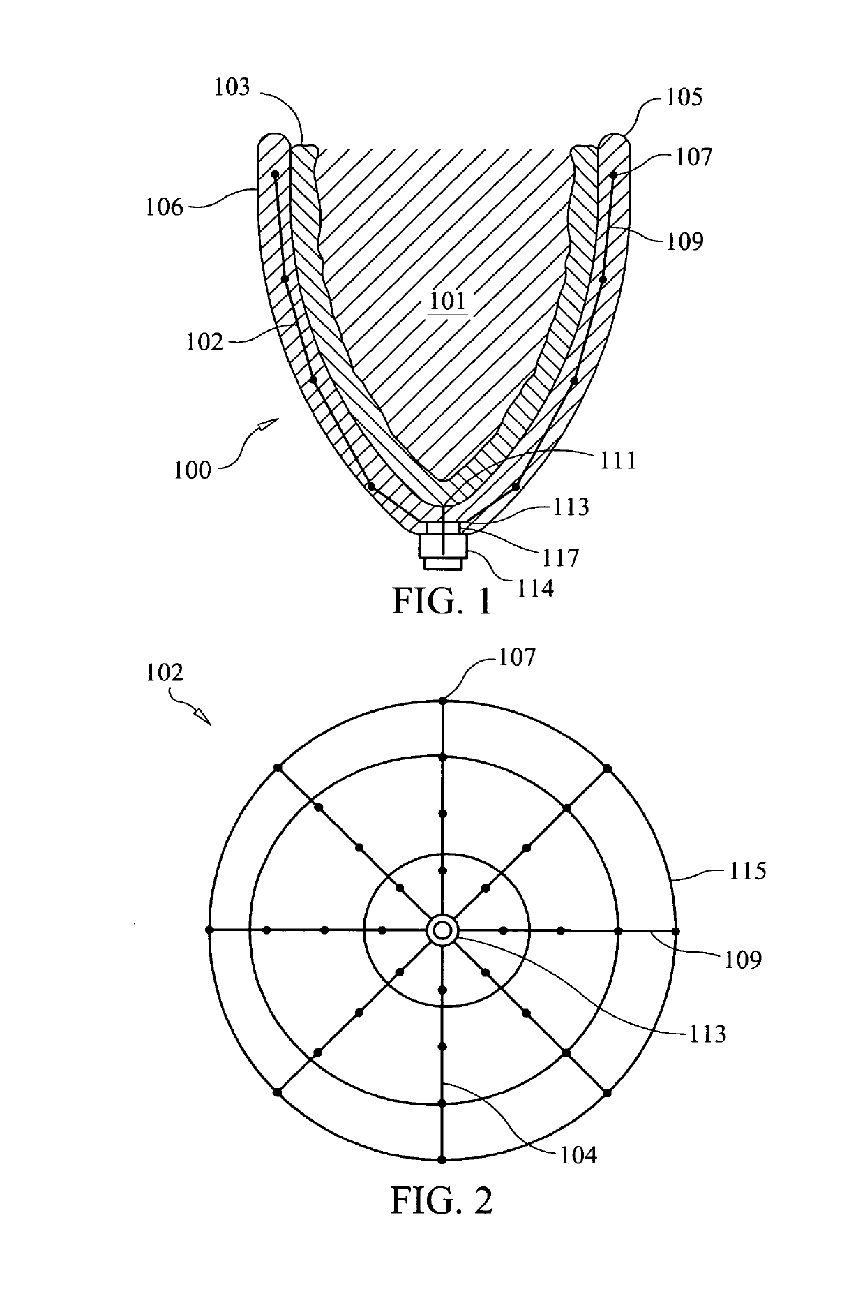
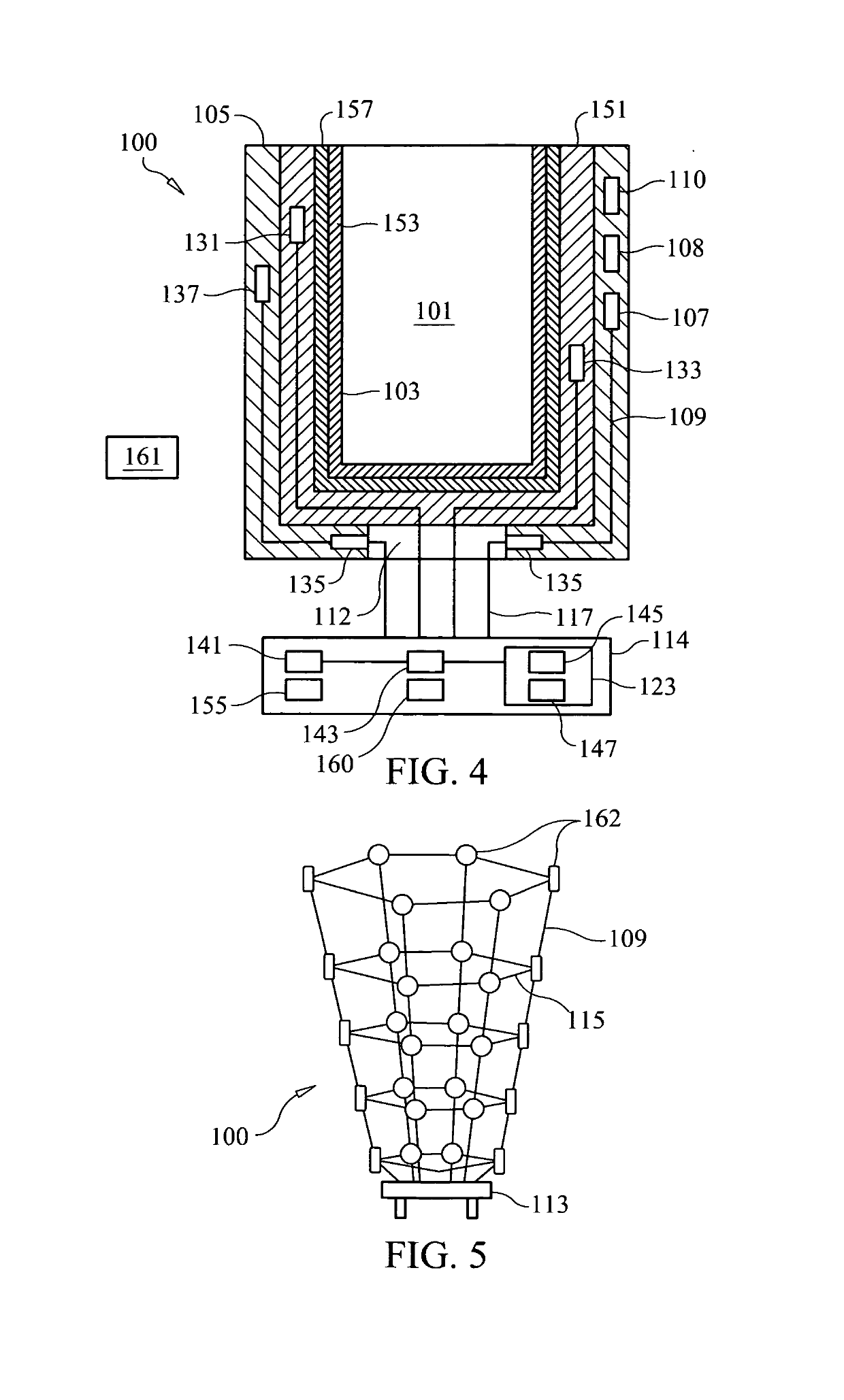
[0091]Referring to FIGS. 1 and 4, two illustrative embodiments of electromagnetic suspension system 100 are shown. In the view shown in FIG. 1, electromagnetic suspension system 100 is installed on residual limb 101. Residual limb 101 is placed within and is in intimate contact with liner 103, which, in this embodiment, is magnetically active. The liner clad residual limb 101 is then placed within prosthetic socket 105 that comprises three-dimensional electromagnet array 102.

[0092]In a preferred embodiment, electromagnet array 102 comprises a plurality of electromagnets 107 that are connected with electrical leads 109. Preferably, array 102 comprises about 10 to about 100 electromagnets and most preferably comprises about 32 electromagnets that are imbedded in sidewalls 106 of prosthetic socket 105 and, in some embodiments, in liner 103. Electrical leads 109 terminate in array hub 113 which is situated in (preferably contained within) adapter connector ring 135 which is preferably d...


PUM


Abstract

A suspension system and method for attaching a prosthetic device to a residual limb. In an illustrative embodiment, the suspension system comprises: a prosthetic socket that is attached to the prosthetic device; a socket adaptor that is incorporated into the prosthetic socket, the socket adaptor comprising a power supply, a microprocessor, and a power switch; a plurality of electromagnets, electropermanent magnets or electroadhesors that are arranged in an array and embedded in said prosthetic socket, each of said electromagnets, electropermanent magnets or electroadhesors being connected to the socket adaptor; a magnetically active liner that is adapted to be in intimate contact with said residual limb and that is fabricated from a magnetically active material; and a locking pin that protrudes from said magnetically active liner and that is adapted to attach the liner to the socket.

Description

CROSS-REFERENCES TO RELATED APPLICATIONS[0001]This application claims the benefit of U.S. Provisional Patent Application No. 61 / 574,956, filed Aug. 12, 2011, the disclosure of which patent application is incorporated by reference as if fully set forth herein.STATEMENT REGARDING FEDERALLY SPONSORED RESEARCH OR DEVELOPMENT[0002]Not ApplicableTHE NAMES OF THE PARTIES TO A JOINT RESEARCH AGREEMENT[0003]Not ApplicableINCORPORATION-BY-REFERENCE OF MATERIAL SUBMITTED ON A COMPACT DISC[0004]Not ApplicableBACKGROUND OF THE INVENTION[0005]This invention relates to prosthetic devices. In particular, the invention relates to a suspension system and method for a prosthetic device.[0006]The suspension system for a prosthetic device serves to attach the device to the user's body. Commonly, a prosthetic device is attached to the remains of an extremity (e.g., a residual limb). It is necessary for the suspension system to ensure a comfortable fit of the prosthesis. It must also allow for the prosthe...

Claims


Application Information

Patent Timeline
Patent Type & Authority Patents(United States)
IPC IPC(8): A61F2/80A61F2/78A61F2/76
CPCA61F2/80A61F2002/7818A61F2/76A61F2/78A61F2/7812A61F2002/701A61F2002/704A61F2002/707A61F2002/7615A61F2002/802
Inventor NEWTON, KAIONE R.ROE, TIMOTHY J.
Owner NEWTON KAIONE R
Why Eureka
Try Eureka