Trailer for a bicycle

a technology for bicycles and trailers, applied in bicycles, bicycle equipment, transportation and packaging, etc., can solve the problems of not being able to be used in the proposed manner with conventional bicycles, affecting the speed of travel, and affecting the handling behavior of bicycles

Active Publication Date: 2019-03-26
BRUGGLI
View PDF12 Cites 0 Cited by
  • Summary
  • Abstract
  • Description
  • Claims
  • Application Information

AI Technical Summary

Problems solved by technology

Most of these trailers are not equipped with a drive or brake and, because of the limited driving power of the cyclist, this has a negative effect on travelling speed and on handling behavior during braking.
Gradients are particularly difficult to negotiate during the ascent and pose a big problem when braking during the descent, in case the trailer has a comparatively large mass.
The disadvantage of the proposed trailer is that it cannot be universally used in the proposed manner with conventional bicycles, since the trailer requires sensor data acquired on the bicycle side.
Thus the trailer can only be used in the proposed operating mode with a bicycle that is fitted with the corresponding sensors to capture the data required for the logic circuit.

Method used


Image

  • Trailer for a bicycle
  • Trailer for a bicycle
  • Trailer for a bicycle

Examples


embodiment 410

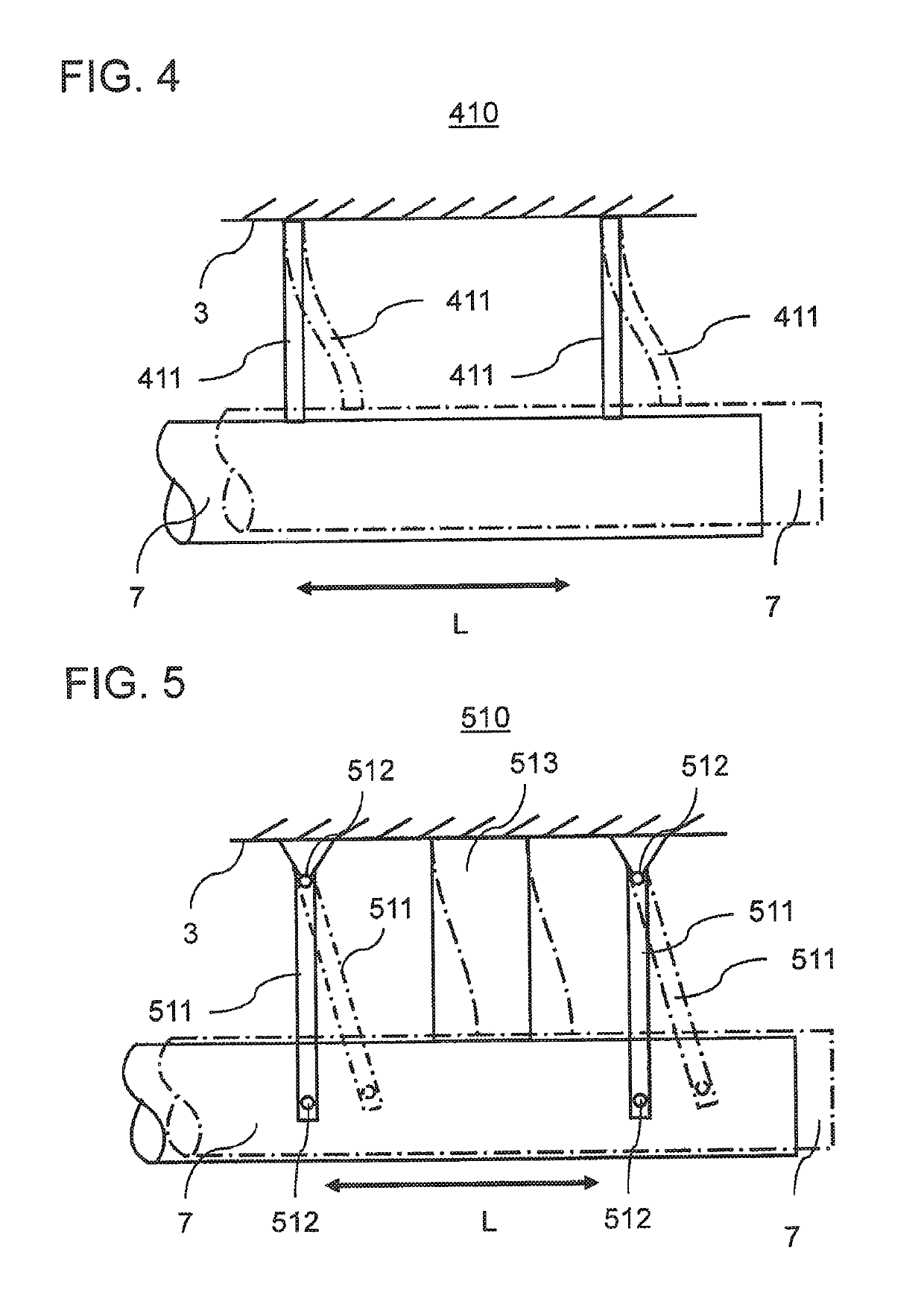
[0065]FIG. 4 shows a detailed view of an embodiment 410 for structural implementation of the decoupling device 10. The decoupling device 410, once again shown in highly schematized form, is realized by means of two bending plates 411, which are made from carbon or a carbon composite. The bending plates 411 are non-rotatably fixed at one end to the trailer body 3, for example to the trailer frame, and at the opposite end to the tow bar 5, especially at the trailer end region 7 of the tow bar 5. The bending plates 411 have low stiffness in the direction of travel or longitudinal direction L and, as a result, can bend transverse to the longitudinal direction L of the trailer, thereby creating the translational degree of freedom.

[0066]The spring stiffness and desired damping are adjusted by the appropriate choice of the geometry and material of the plates 411. Thus the bending plates 411 constitute the functional components 11, 13 and 14 in FIG. 1.

[0067]The broken lines illustrate a sta...

embodiment 510

[0069]FIG. 5 shows an alternative embodiment 510 for the decoupling device 10.

[0070]According to this embodiment, the decoupling device 510 comprises two pivot arms 511, which are each rotatably attached via low-friction rotary bearings to the trailer body 3 at one end and rotatably attached to the tow bar 7 at the opposite end and extend across the longitudinal direction L of the trailer 2.

[0071]Arranged centrically between the two pivot arms 511 is a bending body 513, which is likewise fixed at one end to the trailer body 3 and at the opposite end to the tow bar 7. Thus the bending body 513 likewise extends across the longitudinal direction L of the trailer 2 and is bendable in the longitudinal direction L.

[0072]The spring stiffness and damping of the decoupling device 510 is achieved by means of the additional bending body 513, which undergoes shearing stress under the effect of an acceleration force, while in this case the pivot arms 511 swivel in parallel. This is represented i...


PUM


Abstract

The invention relates to a trailer (2) for a bicycle (1), having a braking device acting on wheel(s) (4) of the trailer (2); a sensor device (12) which supplies a measured variable, which is a measure of an acceleration force acting on the trailer (2) via a tow bar (5); a controller (18) for controlling the braking device and that is configured to act on the braking device, depending on the measured variable determined by the sensor device (12), such that an inertial force of the trailer (2) generated in the pulling mode or during braking of the bicycle (1) is compensated for or is at least reduced; and a decoupling device (10; 410; 510) which is configured for the partial mechanical decoupling of a movement of the bicycle trailer (2) with respect to the bicycle (1) in the longitudinal direction of the bicycle trailer (L).

Description

CROSS-REFERENCE TO RELATED APPLICATIONS[0001]This application is the U.S. National Phase Application of PCT / EP2015 / 01255, filed Jun. 22, 2015, which claims priority to DE 10 2014 009 746.3, filed Jul. 1, 2014, the contents of which applications are incorporated herein by reference in their entireties for all purposes.BACKGROUND OF THE INVENTION[0002]The invention relates to a trailer for a bicycle, having a tow bar for coupling to the bicycle and a braking device acting on one wheel or the wheels of the trailer.[0003]Trailers for bicycles have long been known. Most of these trailers are not equipped with a drive or brake and, because of the limited driving power of the cyclist, this has a negative effect on travelling speed and on handling behavior during braking. Gradients are particularly difficult to negotiate during the ascent and pose a big problem when braking during the descent, in case the trailer has a comparatively large mass. For this reason, the prior art has proposed bi...

Claims


Application Information

Patent Timeline
Patent Type & Authority Patents(United States)
IPC IPC(8): B60D1/62B62M7/14B62K27/00B60T7/20B62M6/50B60D1/00
CPCB60D1/62B60T7/20B62K27/003B62M7/14B62M7/16B62M6/50B62K2207/00B60D2001/003B62J45/42B62J45/414B62K27/14
Inventor GUNTERSWEILER, RETOHASENFRATZ, SIMON
Owner BRUGGLI
Why Eureka
Try Eureka