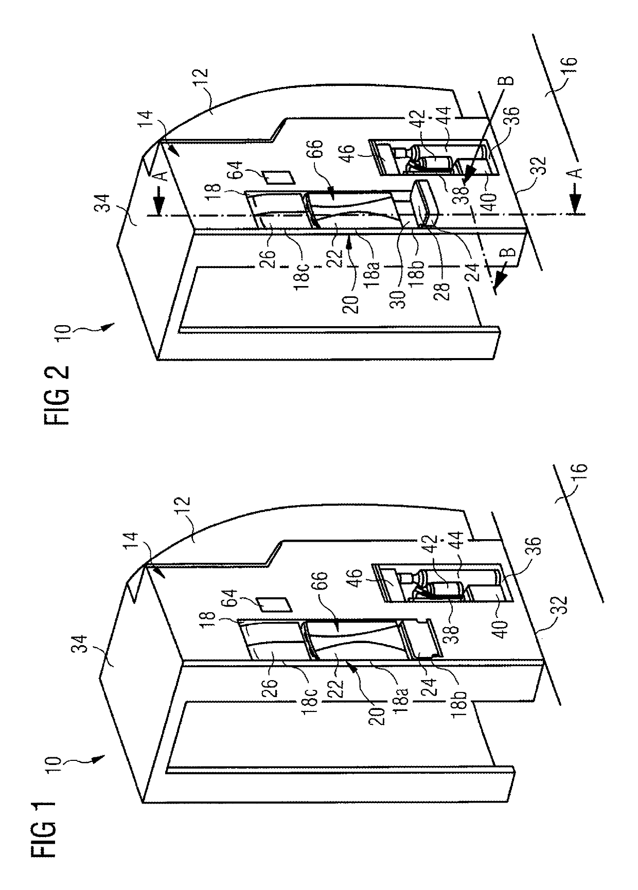
[0007]The flight attendant seat arrangement also comprises a flight attendant seat which has a backrest element and a seat element. The backrest element is fixedly attached to a rear wall of the first receiving recess such that the backrest element extends substantially parallel to the rear wall of the first receiving recess and a portion of the wall of said monument which borders the first receiving recess. Hence, the backrest element is fixed to the wall of the monument in a particularly secure manner. Furthermore, the flight attendant seat is easy to install and easy to service. The backrest element and the seat element are at least partially received within the first receiving recess constructed in the wall of the monument. The flight attendant seat arrangement thus permits optimal utilization of the space available in the passenger cabin of the aircraft. In particular, the space required by the flight attendant seat in an area of the aircraft cabin that borders on the wall of the monument is limited. Compared to a conventional flight attendant seat, the flight attendant seat belonging to the flight attendant seat arrangement therefore has a very much less disruptive effect during the periods in which said seat is not in use, than a conventional flight attendant seat which is known from the prior art.
[0012]Furthermore, the seat element of a flight attendant seat which is constructed as a stand-up seat has a substantially smaller seating surface than a seat element of a conventional flight attendant seat on which a person is able to sit down in a sitting position. Consequently, a flight attendant seat which is constructed as a stand-up seat has a lower space requirement, particularly in its usable position. In addition, the seat element of smaller size which is optimized for a stand-up seat can be received without any difficulty in the second section of the first receiving recess when said seat element is in its inoperative position. A further advantage of a flight attendant seat which is constructed as a stand-up seat consists in the fact that a flight attendant is able to get into an evacuation position more quickly in an emergency, even when he is located on the flight attendant seat, because of his standing posture. In addition, a flight attendant who is located on a flight attendant seat which is constructed as a stand-up seat has a better overview of the cabin than a flight attendant who is located in a sitting position on a conventional flight attendant seat. The loss of comfort for a flight attendant who is using a flight attendant seat constructed as a stand-up seat instead of a conventional flight attendant seat on which he is able to sit down in a sitting position is relatively slight, since the times for which the flight attendant seat is in use during a flight are confined to the takeoff phase and also the landing phase and are consequently comparatively short.
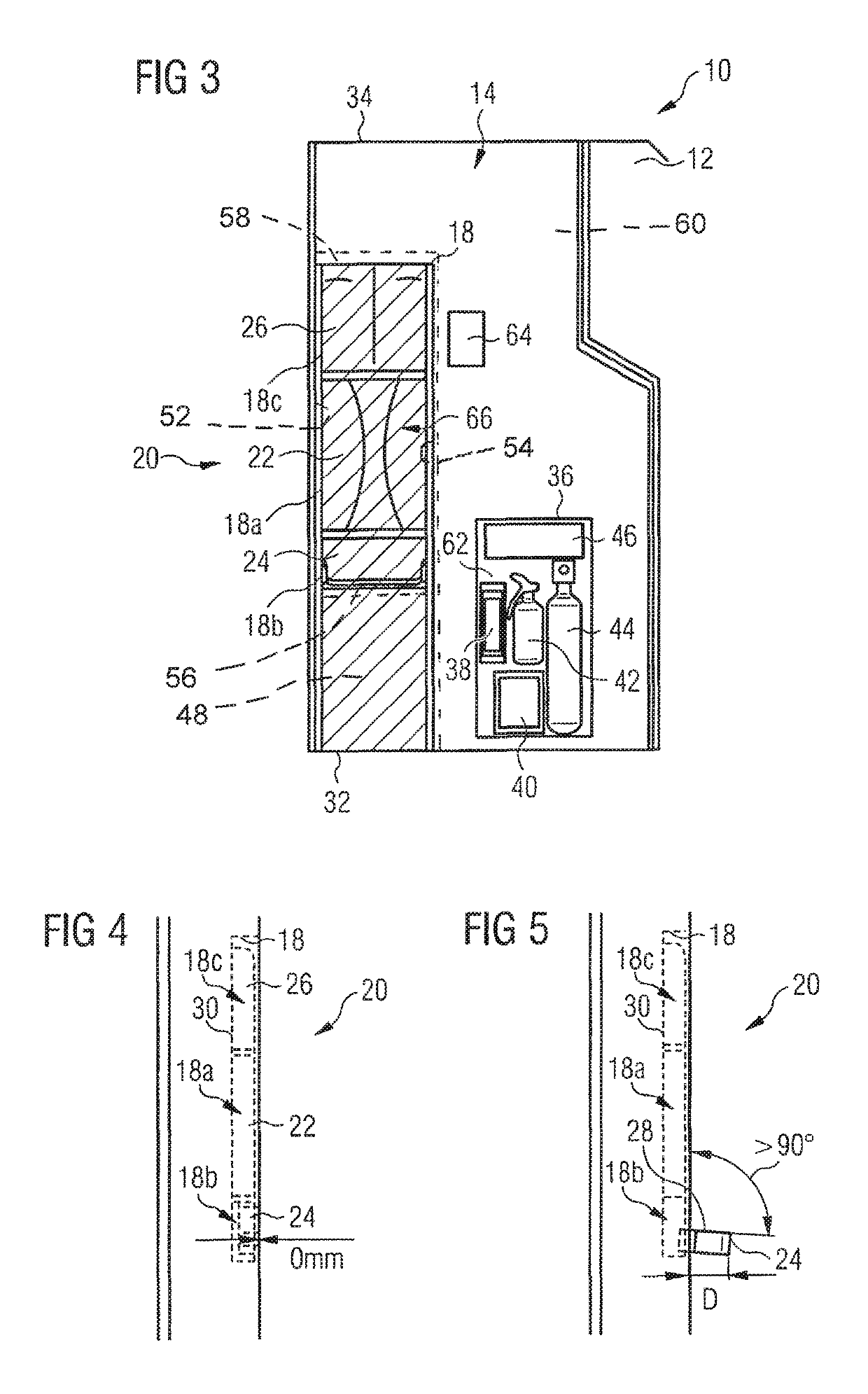
[0013]If the flight attendant seat is constructed as a stand-up seat and the seat element can be tilted, relative to the backrest element, between an inoperative position and a usable position, the angle which the seating surface of the seat element forms with the rear wall of the first receiving recess when said seat element is in its usable position is preferably greater than 90°. Such an orientation of the seat element increases the comfort for a person located on the flight attendant seat which is constructed as a stand-up seat.
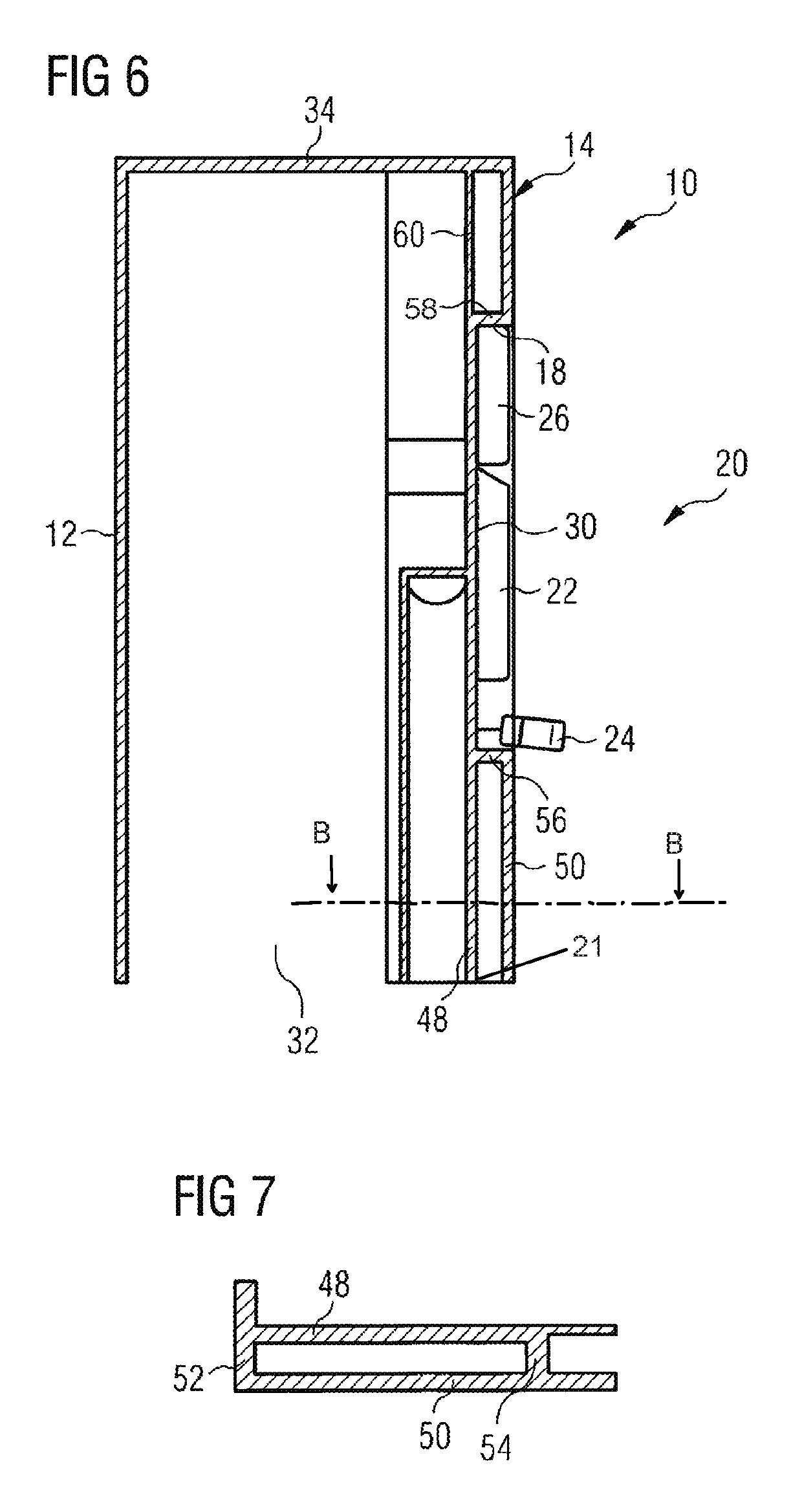
[0018]By configuring the support wall in such a way that it permits the dissipation of all the forces acting upon the flight attendant seat when said seat is in use, it is possible to dispense with an additional support framework for attaching the flight attendant seat to the monument or to a floor of the aircraft cabin. On the contrary, optimal dissipation of force is ensured merely by suitable attachment of the support wall, which extends as far as an end of the monument on a floor side, to the floor of the passenger cabin of the aircraft. Consequently, the flight attendant seat belonging to the flight attendant seat arrangement can be of markedly more lightweight design than a conventional flight attendant seat having a suitable framework for the force-dissipating attachment of said seat within the aircraft cabin. Optimized introduction of force into the support wall is achieved if the wall of the monument in which the first receiving recess for at least partially receiving the components of the flight attendant seat is constructed, and consequently the support wall, are oriented counter to the direction of flight when the flight attendant seat arrangement is installed in an aircraft cabin.
[0021]The wall of the monument may also comprise an inner wall which extends in a manner coplanar with the support wall and substantially parallel to the outer wall. In particular, the inner wall may extend, starting from the second connecting wall, in the direction of a ceiling of the monument as far as said ceiling and, starting from the second side wall, in a direction that faces away from the first receiving recess, from an end of the monument on a floor side as far as the ceiling of said monument. The inner wall preferably has a lower thickness and lower stability than the support wall, and may consequently be of markedly more lightweight design than said support wall. The inner wall preferably extends across those regions of the area of the wall of the monument which do not have to be used for fastening the flight attendant seat and for dissipating forces that act upon said seat in an emergency. The inner wall thus permits a reduction in the overall weight of the flight attendant seat arrangement without the stability of those components of said arrangement which serve for fastening the flight attendant seat and also for dissipating forces acting upon said seat being impaired.

