
Plant control device

a plant control and control device technology, applied in the direction of adaptive control, electric control, instruments, etc., can solve the problems of hardware damage, control performance decline, hardware damage, etc., and achieve the effect of increasing the versatility of a prediction model, and reducing the calculation load on the determination of the target value in the reference governor

Inactive Publication Date: 2019-04-16
TOYOTA JIDOSHA KK
View PDF14 Cites 1 Cited by
  • Summary
  • Abstract
  • Description
  • Claims
  • Application Information

AI Technical Summary

Benefits of technology

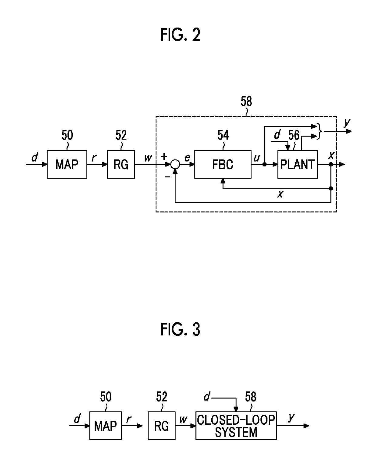
The present disclosure provides a plant control device that can increase versatility for a prediction model and reduce calculation load on correction of a target value of a state quantity of a plant with a constraint imposed on the state quantity. This is achieved by using a prediction model that can describe the dynamic characteristic of a closed-loop system related to feedback control as "dead time+secondary vibration system". The device sets an upper limit constraint for the amount of change in the bed temperature of a temperature control device per unit time, without placing any constraint on the bed temperature of the device. This reduces the calculation load on the final target value when the constraint is applied. The device can predict the predicted value of the state quantity by using an nth-order function model, based on the target value and other variables. The device can also determine the target value satisfying the upper or lower limit constraint by using the evaluation function and a differential function. These functions can be easily calculated without using an iterative calculation. This reduces the calculation load on the determination of the target value, and makes the plant control device more efficient and versatile.

Problems solved by technology

In actual plant control, various constraints in terms of hardware or control may exist with respect to the state quantity of the plant.
When those constraints are not satisfied, hardware damage or a decrease in control performance may be generated.
Thus, when the prediction model cannot be represented by “dead time+secondary vibration system”, the target value may not be corrected.
Thus, when a constraint is imposed on the bed temperature of the DPF, the iterative calculation is needed, thereby leading to an inevitable increase in calculation load on the correction of the target value.

Method used


Image

  • Plant control device
  • Plant control device
  • Plant control device

Examples


first embodiment

Features of First Embodiment

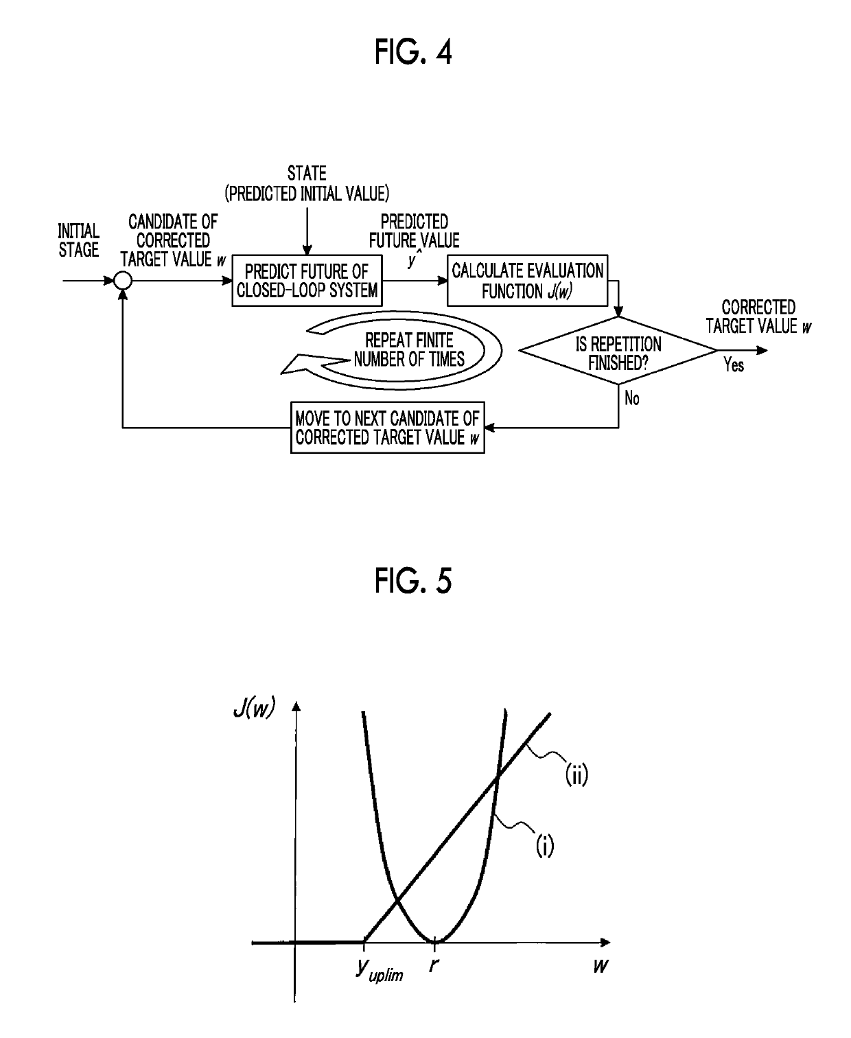
[0056]The first embodiment performs optimal solution search using a geometric structure of the gradients (derivative values) of each term of the evaluation function J(w) in order to decrease the amount of calculation for selection of the corrected target value w. FIG. 5 is a diagram schematically illustrating the evaluation function J(w) represented in General Formula (2) on an xy plane having the corrected target value w as an x axis and the evaluation function J(w) as a y axis, with the evaluation function J(w) decomposed into the first term on the right-hand side and the second term on the right-hand side. A part (i) of FIG. 5 corresponds to the first term on the right-hand side, and a part (ii) of FIG. 5 corresponds to the second term on the right-hand side. As illustrated in FIG. 5, the first term (i) on the right-hand side is represented as a quadratic curve with J(w)=0 when the corrected target value w is equal to the initial target value r. The se...

second embodiment

Features of Second Embodiment

[0074]As in the first embodiment, the second embodiment performs optimal solution search using a geometric structure of the gradient of the evaluation function J(w). FIG. 9 is a diagram schematically illustrating the evaluation function J(w) represented in General Formula (2) on an xy plane having the corrected target value w as an x axis and the evaluation function J(w) as a y axis, with the evaluation function J(w) decomposed into the first term on the right-hand side and the second term on the right-hand side. A part (i) of FIG. 9 corresponds to the first term on the right-hand side, and a part (ii) of FIG. 9 corresponds to the second term on the right-hand side. As illustrated in FIG. 9, the first term (i) on the right-hand side is represented as a quadratic curve with J(w)=0 when the corrected target value w is equal to the initial target value r. The part heretofore is the same as in the first embodiment. The difference from the first embodiment is...

third embodiment

Features of Third Embodiment

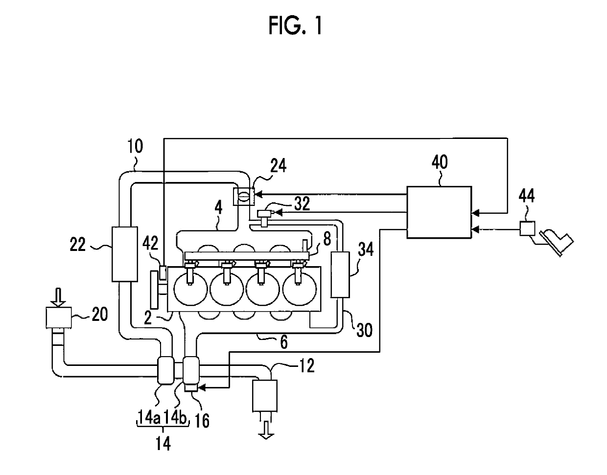
[0091]In the first embodiment, an upper limit constraint in terms of hardware or control is imposed on the boost pressure. Meanwhile, in the third embodiment, a lower limit constraint in terms of hardware or control is imposed on the boost pressure. The evaluation function J(w) when the lower limit constraint is set is described by, for example, General Formula (4).

J(w)=∥r−w∥2+ρ max{ylo lim−ŷ,0}  (4)

[0092]The first term on the right-hand side of General Formula (4) is the same function as the first term on the right-hand side of General Formula (2). The second term on the right-hand side of General Formula (4) is a function that takes the future value y^ as a variable. The function adds a penalty to an objective function when the future value y^ violates a lower limit constraintylolim. The function takes zero when the future value y^ does not violate the lower limit constraint ylolim, and has a greater value as the amount of violation of the lower limit c...


PUM


Abstract

A plant control device includes a feedback controller that determines a control input of a plant, and a reference governor that corrects an initial target value and outputs the corrected initial target value to the feedback controller. The reference governor determines a target value satisfying an upper limit constraint to be a target value candidate that minimizes a value of an evaluation function. The reference governor determines the target value satisfying the upper limit constraint to be a value of the upper limit constraint when a value acquired by substituting, with the value of the upper limit constraint, a variable of a differential function acquired by differentiating the evaluation function with respect to the target value candidate is greater than or equal to zero.

Description

CROSS-REFERENCE TO RELATED APPLICATIONS[0001]This application claims priority to Japanese Patent Application No. 2016-203623 filed on Oct. 17, 2016, the entire contents of which are incorporated herein by reference.BACKGROUND1. Technical Field[0002]The present disclosure relates to a plant control device.2. Description of Related Art[0003]When a general plant control device is provided with a target value related to a control output of a plant, the plant control device determines a control input of a plant by feedback control that causes the control output to follow the target value. In actual plant control, various constraints in terms of hardware or control may exist with respect to the state quantity of the plant. When those constraints are not satisfied, hardware damage or a decrease in control performance may be generated. Constraint satisfaction is one type of significant performance demanded for plant control, like causing the control output to follow the target value.[0004]O...

Claims


Application Information

Patent Timeline
Patent Type & Authority Patents(United States)
IPC IPC(8): F02D41/14F01N3/035G06F17/13G05B13/04
CPCF02D41/1406F01N3/035F02D41/1441G05B13/04G06F17/13G05B13/048Y02T10/144F02D2041/1412F02D2041/1433F01D17/14F02B37/24Y02T10/12F02D41/0235F02D41/0007F02D41/0052F02D41/1401F02B37/00F02D41/04F02D41/30F02D43/04G05B13/02
Inventor NAKADA, HAYATO
Owner TOYOTA JIDOSHA KK
Learn More