
Ligament assembly

a technology of ligament and assembly, which is applied in the field of ligament assembly, can solve the problems of inability to match the properties of artificial fibres, the loss of both cruciate ligaments, and the extreme, and achieve the effect of increasing the tear out for

Active Publication Date: 2019-04-23
BIOMET UK HEALTHCARE
View PDF16 Cites 1 Cited by
  • Summary
  • Abstract
  • Description
  • Claims
  • Application Information

AI Technical Summary

Benefits of technology

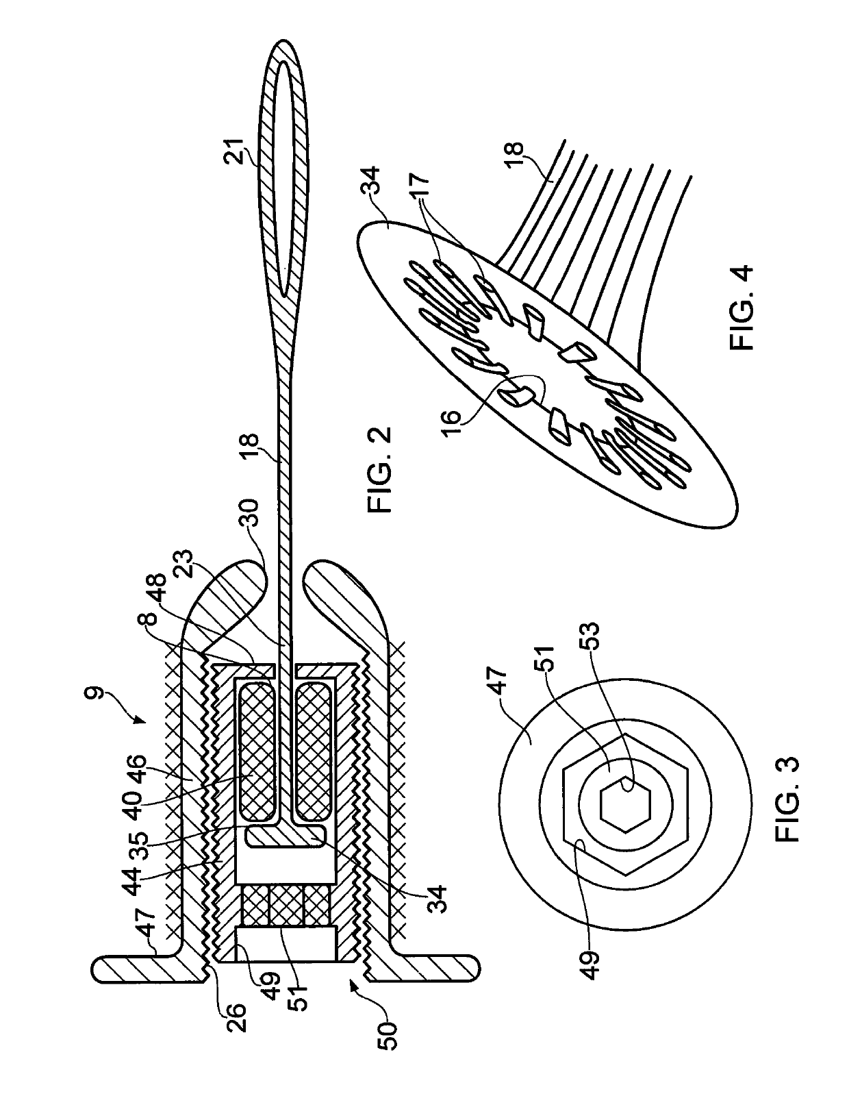
[0031]The resilient element may have a stiffness approximating that of a natural ligament that is to be replaced. In this manner, the resilient element may assist in replicating the natural characteristics of the joint. The resilient element may have linear or non-linear stiffness characteristics which may be achieved by methods known in the art. The stiffness of the resilient element may be in a range of 3 N / mm to 40 N / mm.
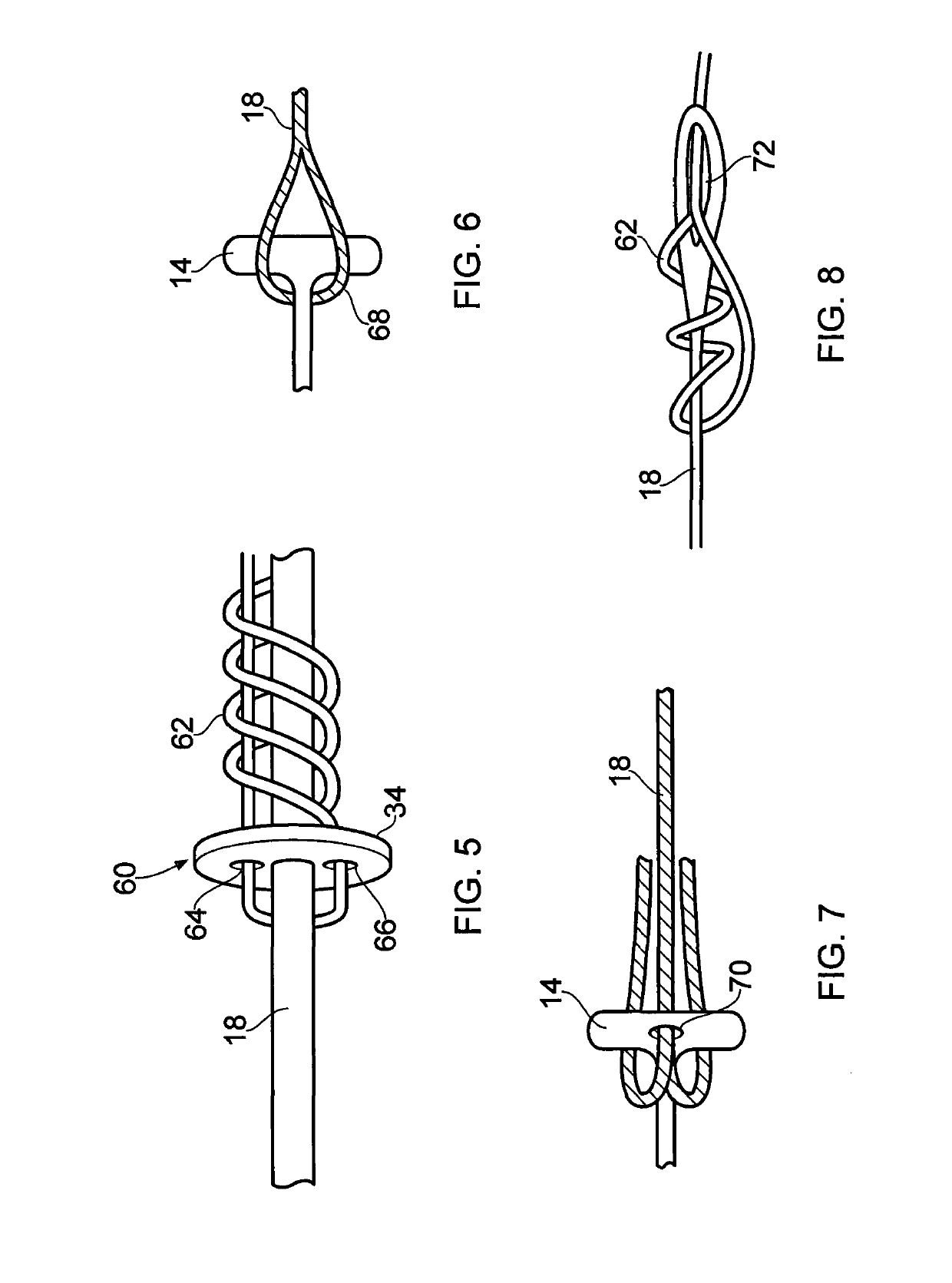
[0050]The ligament, part ligament, thread or cord may extend through the bore and be tied off to prevent it passing back through the bore. The ligament, part ligament, thread or cord may be wound around the anchor and pass back over itself, so that tension in the ligament, part ligament, thread or cord causes the ligament, part ligament, thread or cord to grip itself more tightly, and thereby to increase the tear out force required to pull the ligament away from the ligament anchor.

Problems solved by technology

To date, it has been impossible to match these properties using artificial fibres.
However, if surrounding bone tissue is significantly diseased or damaged, it may be necessary to remove both the natural ligament and the adjacent bone tissue and replace them with prosthetic components.
When implanting a total joint replacement prosthesis, both cruciate ligaments are often lost.
However, it has proved extremely difficult to replicate the natural kinematics of a joint without the presence of naturally functioning ligaments.
Particularly where such a prosthesis uses a mobile bearing, there will be an increased risk of dislocation in the event of joint distraction, if one or more of the ligaments of the knee are diseased or otherwise damaged.

Method used


Image

  • Ligament assembly
  • Ligament assembly
  • Ligament assembly

Examples


Embodiment Construction

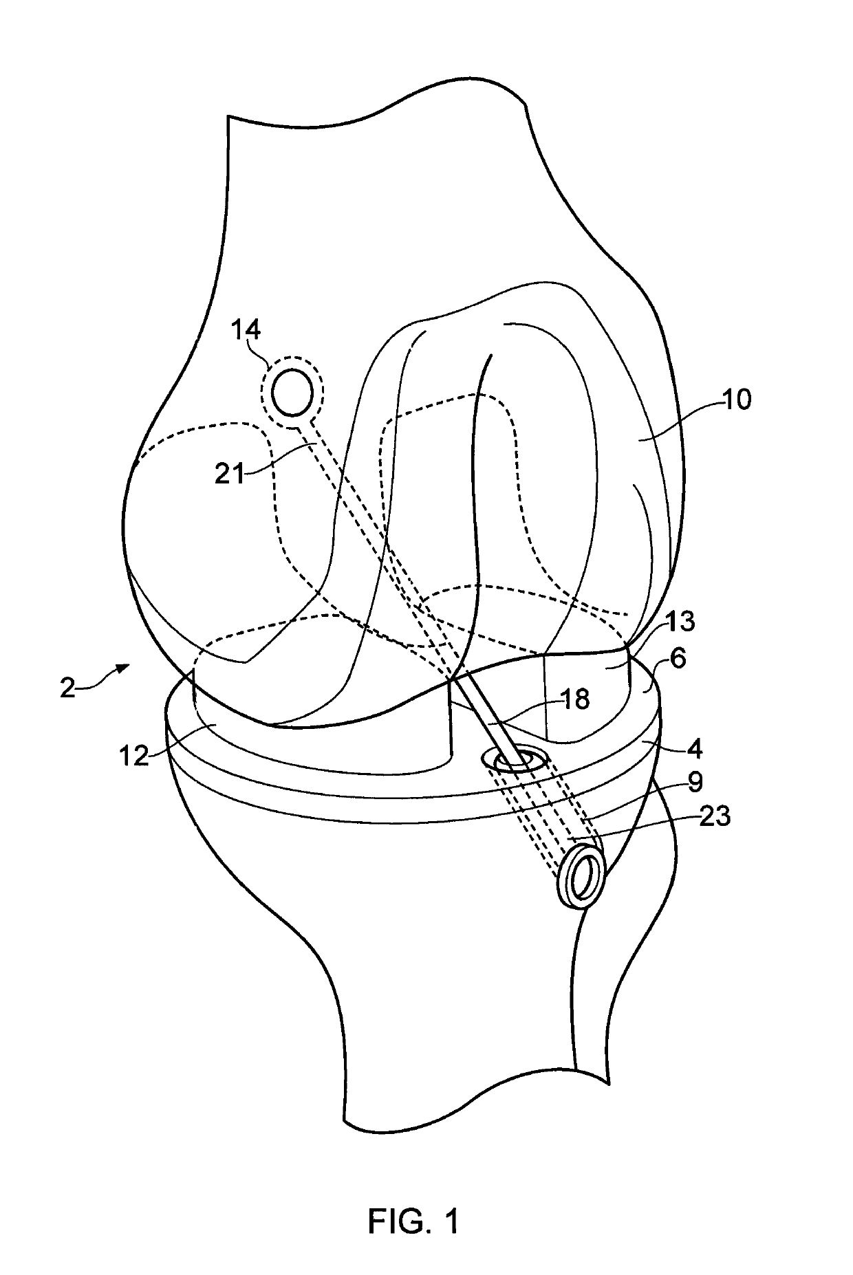
[0067]FIG. 1, illustrates a knee joint in which is implanted a total joint replacement prosthesis and a ligament assembly. However, it will be appreciated that the ligament assembly described herein can be used with a partial joint replacement prosthesis, or on a knee joint without any form of joint replacement prosthesis.

[0068]Referring to FIG. 1, a knee joint is fitted with a prosthesis 2 comprising a tibial component 4 having a tibial tray 6 integrally formed with a stem (not shown), a femoral component 10 and a pair of bearing components 12, 13. The bearing components 12, 13 separate the tibial component 4 and femoral component 10, and are formed with proximal and distal bearing surfaces which engage corresponding bearing surfaces on the tibial tray 6 and on the femoral component 10. These various bearing surfaces enable the tibial component 4 to rotate and translate relative to the femoral component 10. The bearing components 12, 13 may, for example, be meniscal bearing compone...


PUM


Abstract

A ligament assembly comprising a first ligament anchor (9) connected to a second ligament anchor (14) by a ligament (18) a resilient element (40) being associated with the first ligament anchor (9) and a ligament tension adjuster (44, 50) being associated with the second ligament anchor (14). The resilient element (40) may be disposed within the first ligament anchor (9) and the ligament tension adjuster (44, 50) may be disposed within the second ligament anchor (14).

Description

CLAIM OF PRIORITY[0001]This application is a U.S. National Stage Filing under 35 U.S.C. 371 from International Application No. PCT / GB2014 / 052348, filed on 31 Jul. 2014, published as WO 2015 / 022491 A1, which claims the benefit of United Kingdom Application No. 1314408.4 filed on 12 Aug. 2013, the benefit of priority of each of which is claimed hereby, and each of which are incorporated by reference herein in its entirety.[0002]This invention relates to improvements in ligament assemblies and particularly, although not exclusively, relates to improving the connection between a ligament and a ligament anchor.BACKGROUND[0003]It is known to implant an artificial / prosthetic ligament to replace a natural ligament which has become damaged. Conventional artificial ligaments are formed from strands or bundles of artificial fibres which may be woven and / or aligned to form a flexible member which is substantially uniform in size and is resilient along its length.[0004]A natural ligament exhibit...

Claims


Application Information

Patent Timeline
Patent Type & Authority Patents(United States)
IPC IPC(8): A61F2/08A61F2/38
CPCA61F2/0811A61F2/08A61F2/3886A61F2002/087A61F2002/0835A61F2002/0852A61F2002/0864A61F2002/0882A61F2250/0012
Inventor MURRAY, DAVID WYCLIFFEDODD, CHRISTOPHERO'CONNOR, JOHNLLOYD, RUSSELLKAHN, MOHAMMED IMRAN
Owner BIOMET UK HEALTHCARE
Learn More