Insulating concrete form system

a concrete form and concrete technology, applied in the direction of walls, shaping building parts, forms/shuttering/falseworks, etc., can solve the problems of high manufacturing cost, inoperable or subjected to breakage, and add to the final cost of the finished concrete wall structure in time to adequately, etc., to achieve the effect of cost saving and easy removal

Active Publication Date: 2019-04-23
STRONGHOLD INSULATION SYST INC
View PDF48 Cites 2 Cited by
  • Summary
  • Abstract
  • Description
  • Claims
  • Application Information

AI Technical Summary

Benefits of technology

[0013]In order to overcome the numerous drawbacks apparent in the prior art, an insulating concrete form (ICF) system has been devised for constructing and fabricating poured concrete walls in building structures, particularly incorporating interlocking foam panels operating in conjunction with panel spacing ties that effect efficient and economical manufacture, shipping and onsite assembly of the ICF system.
[0014]It is an object of the present invention to provide an ICF system that utilizes panel spacing ties having structural attributes that permit assembly and connection to the foam panels during the manufacturing phase yet allow for compactness for economical shipping of the ICF system, while fulfilling an opportunity to openly expand or separate apart the foam panels to form a strengthened interior cavity constituting the form of the concrete wall structure without the extensive interaction and effort of onsite field personnel.

Problems solved by technology

It is often the case that these structural oversights within the foam panel are generally addressed at a later time during the construction phase of the building structure and completed by personnel other than by those responsible for erecting the ICF system and, consequently, can significantly add to the final cost of the finished concrete wall structure in terms of time to adequately accommodate the foregoing features at a moment of time well beyond placement of the ICF system.
Although Titishov and Wostal each disclose a novel approach to fulfill compactness of the ICF system for economical shipping thereof and offer a modest degree of simplicity for onsite assembly of the ICF system, there are inherent disadvantages associated with each approach, most notably being attributed to the multitude of intricate components constituting the panel spacing tie that perhaps can subject it to failure in the backdrop of high manufacturing costs.
It is conceivable within the context of their designs that an appreciable amount debris and other foreign matter could find its way within the intricate structure of the sub-components during onsite assembly of the ICF system that can unduly compromise the range of motion or sliding movement needed to effect complete and accurate assembly of the ICF system and, in instances of sizeable debris or amounts thereof interacting with the sub-components in particular, can render them completely inoperable or subject them to breakage.
Furthermore, since structural portions of the panel spacing tie, such as the flange components thereof, permanently reside or are formed within the matrix of the foam panel during the manufacturing phase, any breakage of the sort mentioned above may require extensive repair or render the foam block assembly entirely useless, thus unnecessarily adding to the overall time and cost in completing the finished wall structure.

Method used


Image

  • Insulating concrete form system
  • Insulating concrete form system
  • Insulating concrete form system

Examples


Embodiment Construction

[0081]While this invention is susceptible of being embodied in many different forms, the preferred embodiment of the invention is illustrated in the accompanying drawings and described in detail hereinafter with the understanding that the present disclosure purposefully exemplifies the principles of the present invention and is not intended to unduly limit the invention to the embodiments illustrated and presented herein. The present invention has particular utility as a system that fulfills use of insulating concrete forms for the efficient and economical development and fabrication of poured concrete walls for building structures.

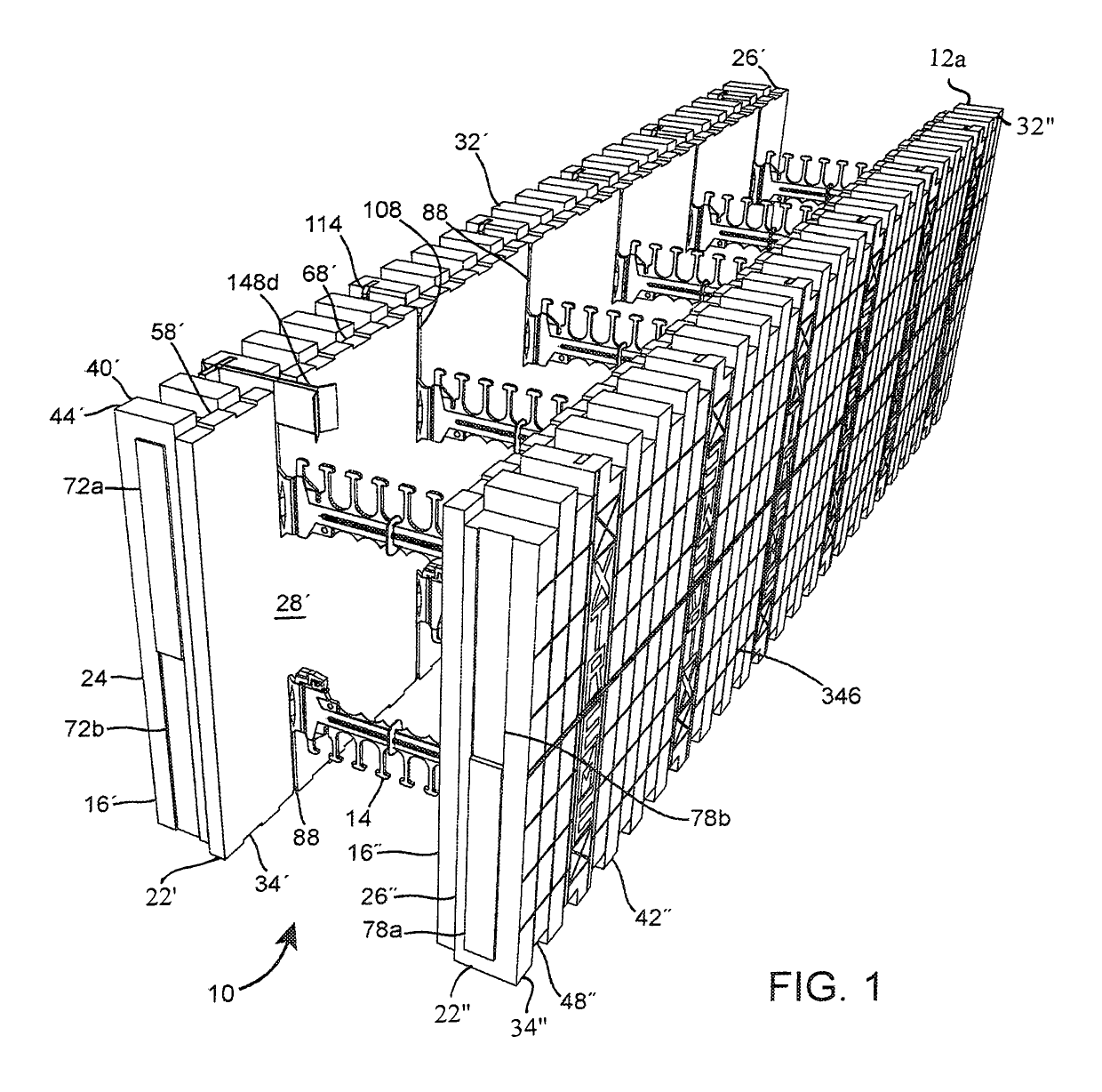
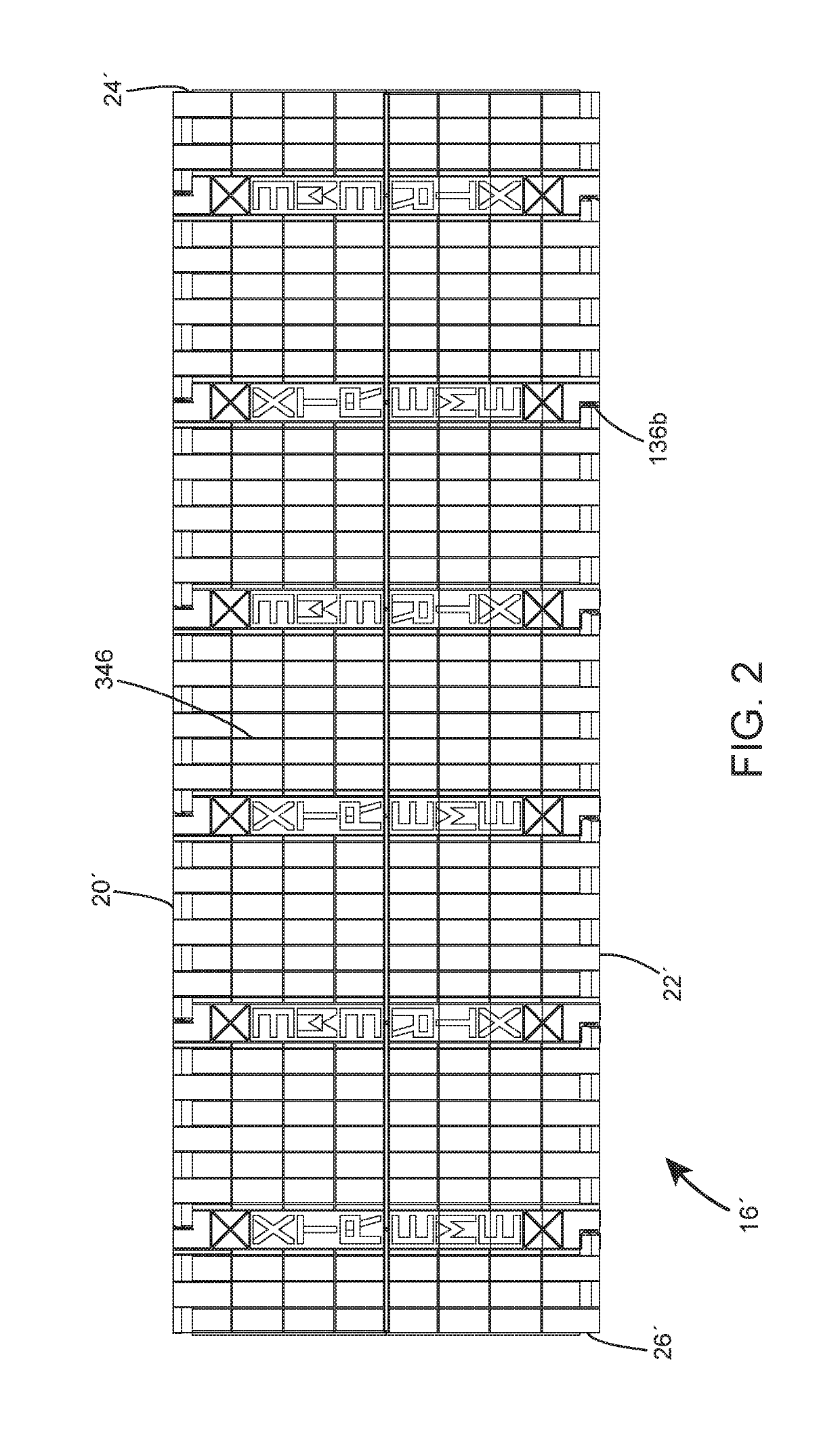
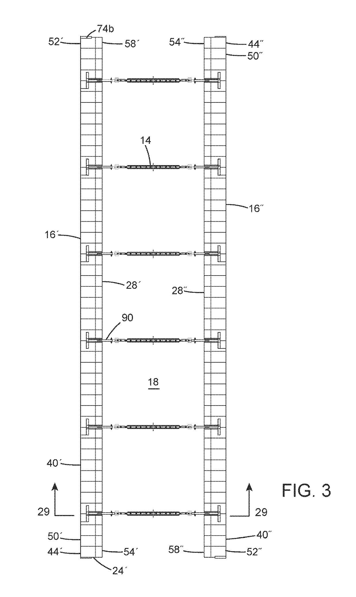
[0082]Referring now to FIGS. 1 and 54, there is shown generally at 10 an insulating concrete form (ICF) system comprising longitudinal and corner block assemblies 12a, 12b respectively directed to forming and fabricating straight-line and corner wall structures. Each longitudinal block assembly is generally shown in FIG. 3 as comprising a plurality of pan...


PUM


Abstract

The insulating concrete form system includes longitudinal and corner block assemblies each having a pair of side panels configured with tie receivers interacting with panel spacing ties to hold the side panels in an opposing manner and leading edges with an alternating arrangement of projections and recesses for interlocking with neighboring block assemblies. Each panel spacing tie includes a mid-support section interposing in between and connecting to a pair of end sections by a living hinge with each end section being configured with a flange member for placement within an opposing spatial wedge of the tie receiver, whereby the living hinge possesses the capability of allowing the side panels to move inwardly toward one another in a racked position to yield compactness of the longitudinal block assembly for economical transport. The corner block assembly also includes corner panel spacing ties to supplementally reinforce its structure to withstand hydrostatic blowout caused by poured concrete.

Description

CROSS-REFERENCE TO RELATED APPLICATIONS[0001]This application claims the benefit of U.S. Provisional Patent Application No. 62 / 332,843, filed May 6, 2016, entitled “Insulating Concrete Form System,” the disclosures of which, including all attached documents, are incorporated herein by reference in their entirety for all purposes.FIELD OF THE INVENTION[0002]The present invention generally relates to an Insulating Concrete Form (ICF) systems directed to the construction and fabrication of poured concrete walls in building structures and, more specifically, to improvements to the foam panels and associated panel spacing ties that appreciably allow for efficient manufacturing, economical shipping and field assembly of the ICF system.BACKGROUND OF THE INVENTION[0003]Traditional methods of constructing and fabricating poured concrete walls typically involve the usage of forms made from sheets of plywood, solid wood, metal, or plastic composites, whereby the sheets are held apart a predete...

Claims


Application Information

Patent Timeline
Patent Type & Authority Patents(United States)
IPC IPC(8): E04B2/28E04G11/06E04G17/07E04G9/10E04B2/86E04G9/02E04G17/075E04G17/06
CPCE04B2/8635E04B2/8641E04G9/02E04G9/10E04G11/06E04G17/0758E04B2002/867E04B2002/8694E04G2017/0638
Inventor STEWART, COOPER E.
Owner STRONGHOLD INSULATION SYST INC
Why Eureka
Try Eureka